содержание .. 541 542 543 544 ..
Nissan Murano Z51. Manual - part 543
EC-180
< DTC/CIRCUIT DIAGNOSIS >
[VQ35DE]
P0128 THERMOSTAT FUNCTION
P0128 THERMOSTAT FUNCTION
DTC Logic
INFOID:0000000005536591
DTC DETECTION LOGIC
NOTE:
If DTC P0128 is displayed with DTC P0300, P0301, P0302, P0303, P0304, P0305 or P0306, first perform
the trouble diagnosis for DTC P0300, P0301, P0302, P0303, P0304, P0305, P0306. Refer to
Engine coolant temperature has not risen enough to open the thermostat even though the engine has run long
enough.
This is due to a leakage in the seal or the thermostat being stuck open.
DTC CONFIRMATION PROCEDURE
1.
PRECONDITIONING
If DTC Confirmation Procedure has been previously conducted, always perform the following before conduct-
ing the next test.
1.
Turn ignition switch OFF and wait at least 10 seconds.
2.
Turn ignition switch ON.
3.
Turn ignition switch OFF and wait at least 10 seconds.
TESTING CONDITION:
• For best results, perform at ambient temperature of –10
°
C (14
°
F) or higher.
• For best results, perform at engine coolant temperature of –10
°
C (14
°
F) to 56
°
C (133
°
F).
• Before performing the following procedure, do not add fuel.
>> GO TO 2.
2.
PERFORM DTC CONFIRMATION PROCEDURE
With CONSULT-III
1.
Turn A/C switch OFF.
2.
Turn blower fan switch OFF.
3.
Turn ignition switch ON.
4.
Select “COOLAN TEMP/S” in “DATA MONITOR” mode with CONSULT-III.
5.
Check the indication of “COOLAN TEMP/S”
If it is below 56
°
C (133
°
F), go to next step.
If it is above 56
°
C (133
°
F), cool down the engine to less than 56
°
C (133
°
F). Then go to next steps.
6.
Start engine.
7.
Drive vehicle for 10 consecutive minutes under the following conditions.
CAUTION:
Always drive vehicle at a safe speed.
NOTE:
If “COOLAN TEMP/S” increases to more than 75
°
C (167
°
F) within 10 minutes, turn ignition switch
OFF because the test result will be OK.
8.
Check 1st trip DTC.
With GST
Follow the procedure “With CONSULT-III” above.
Is 1st trip DTC detected?
YES
>> Go to
NO
>> INSPECTION END
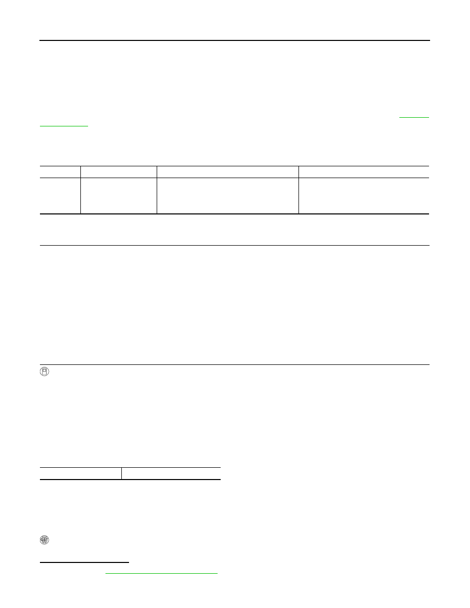
DTC No.
Trouble diagnosis name
DTC detecting condition
Possible cause
P0128
Thermostat function
The engine coolant temperature does not reach
to specified temperature even though the en-
gine has run long enough.
• Thermostat
• Leakage from sealing portion of thermo-
stat
• Engine coolant temperature sensor
VHCL SPEED SE
More than 56 km/h (35 MPH)