содержание .. 488 489 490 491 ..
Nissan Murano Z51. Manual - part 490
DLN-94
< REMOVAL AND INSTALLATION >
[REAR FINAL DRIVE: R145]
FRONT OIL SEAL
REMOVAL AND INSTALLATION
FRONT OIL SEAL
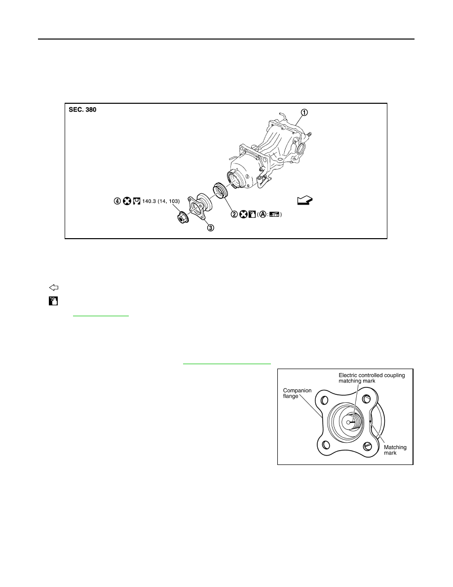
Exploded View
INFOID:0000000005514252
Removal and Installation
INFOID:0000000005514253
REMOVAL
1.
Remove rear propeller shaft. Refer to
2.
Put matching mark on the thread edge of electric controlled cou-
pling. The matching mark should be in line with the matching
mark on companion flange.
CAUTION:
For matching mark, use paint. Never damage electric con-
trolled coupling.
1.
Final drive assembly
2.
Front oil seal
3.
Companion flange
4.
Companion flange lock nut
A.
Oil seal lip
: Vehicle front
: Apply gear oil.
Refer to
for symbols not described above.
JPDID0004GB
PDIA0455E