Nissan Murano Z51. Manual - part 484


  Главная      Nissan     Nissan Murano Z51 (2010 year) - Service Manual


поиск по сайту            


содержание   ..  482  483  484  485   ..


Nissan Murano Z51. Manual - part 484


DLN-70

< UNIT DISASSEMBLY AND ASSEMBLY >

[TRANSFER: TY20A]

DRIVE PINION

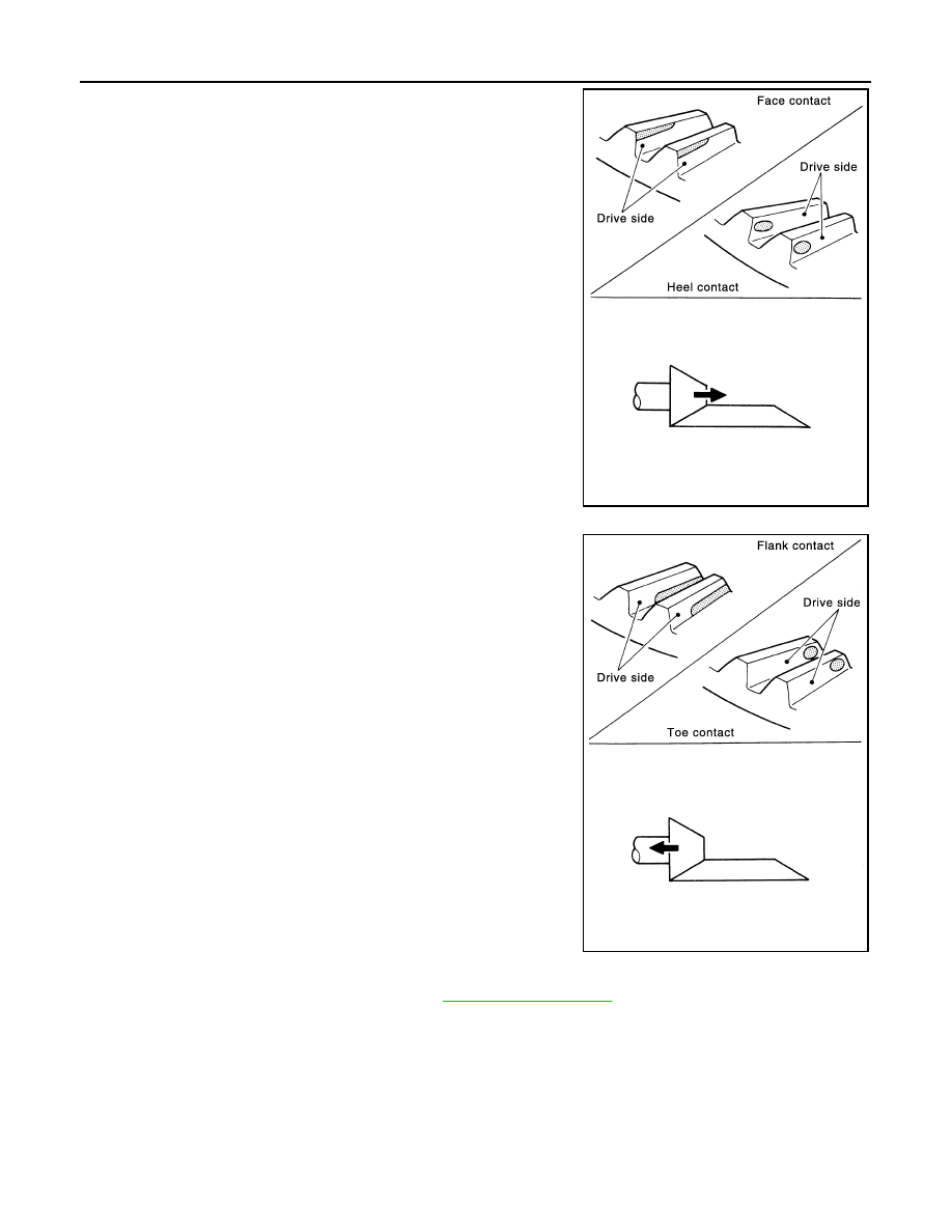
• If the tooth contact is near the face (face contact), or near the

heal (heel contact), thin the pinion sleeve shims to move the
drive pinion closer to the drive gear.

• If the tooth contact is near the flank (flank contact), or near the

toe (toe contact), thicken the pinion sleeve shims to move the
drive pinion farther from the drive gear.

PINION BEARING PRELOAD

1.

Remove the pinion sleeve assembly. Refer to 

DLN-65, "Disassembly"

.

2.

Rotate the companion flange back and forth 2 to 3 times. Check for unusual noise, rotation malfunction,
and other malfunctions.

3.

Rotate the companion flange at least 20 times to check for smooth operation of the bearing.

SDIA0518E

SDIA0519E

DRIVE PINION

DLN-71

< UNIT DISASSEMBLY AND ASSEMBLY >

[TRANSFER: TY20A]

C

E

F

G

H

I

J

K

L

M

A

B

DLN

N

O

P

4.

Measure the drive pinion bearing preload with the preload
gauge (A) [SST: ST3127S000 (J-25765-A)].

CAUTION:

• Every rotational part shall rotate smoothly with the speci-

fied gear oil.

• Preload torque differs before disassembly and after reas-

sembly.

• If measured value is out of the specification, disassemble the pin-

ion sleeve assembly to check and adjust each part.

TOTAL PRELOAD

1.

Measure pinion bearing preload torque (P

1

). Refer to 

DLN-79, "Preload Torque"

.

2.

Install the pinion sleeve shims and pinion sleeve assembly.

3.

Rotate the companion flange at least 20 times to check for smooth operation of the bearing.

4.

Measure the total preload with the preload gauge (A) [SST:
ST3127S000 (J-25765-A)].

CAUTION:

Preload torque differs before disassembly and after reas-
sembly.

• If measured value is out of the specification, disassemble it to

check and adjust each part. When measuring the total preload
torque after the disassembly, measure it with the transfer case oil seals and gear ring oil seals removed,
then install the oil seals.

COMPANION FLANGE RUNOUT

1.

Fit a dial indicator onto the companion flange face (inner side of
the propeller shaft mounting bolt holes).

2.

Rotate the companion flange to check for runout.

3.

Fit a test indicator to the inner side of the companion flange
(socket diameter).

4.

Rotate the companion flange to check for runout.

5.

If the runout value is outside the repair limit, follow the procedure below to adjust.

a.

While changing the phase between companion flange and drive pinion gear by 90

°

 at a time, check runout

and determine which phase angle minimizes the runout.

b.

If the runout value is still outside of the limit after the phase has been changed, replace the companion
flange.

c.

If the runout is out of the specification after replacement of companion flange, adjust the assembly status
of the pinion bearings and drive pinion gear, or replace the pinion bearings.

Standard

Preload torque

: Refer to 

DLN-79, "Preload Torque"

.

JPDIE0023ZZ

Standard

Total Preload torque

: Refer to 

DLN-79, "Preload 

Torque"

.

JPDIE0024ZZ

Limit

Companion flange runout

: Refer to 

DLN-79, "Com-

panion Flange Runout"

.

Limit

Companion flange runout

: Refer to 

DLN-79, "Com-

panion Flange Runout"

.

JPDIE0090ZZ

DLN-72

< UNIT DISASSEMBLY AND ASSEMBLY >

[TRANSFER: TY20A]

DRIVE PINION

SELECTING ADJUSTING SHIM

Measurement point

Gear Ring Bearing Adjusting Shim (Transfer Case Side)

1.

Measure F, H, I, R and U shown in the measurement points.

2.

Convert the values F, H, I, R and U according to the standards below.

3.

Check dimension Z on the drive gear side face.
NOTE:
Dimension Z indicates the difference between the optimum engagement and the standard dimensions in
increments of 0.01mm (0.0004 in) written on the drive gear side face.

4.

Use the formula below to calculate gear ring bearing adjusting shim (transfer case side) thickness T

1

.

5.

Select the gear ring bearing adjusting shim (transfer case side).

CAUTION:

• Only one adjusting shim can be selected.
• If no adjusting shim with the calculated value is available, select the thicker and closest one.

Gear Ring Bearing Adjusting Shim (Adapter Case Side)

1.

Measure F, H, J, K, U and V shown in the measurement points.

2.

Convert the values F, H, J, K, U and V according to the standards below.

JPDIE0034ZZ

1.

Gear ring bearing (transfer case 
side)

2.

Gear ring bearing (adapter case 
side)

3.

Pinion front bearing

4.

Transfer case

5.

Pinion sleeve

6.

Adapter case

7.

Gear ring

F:

Value obtained by subtracting 163.00 mm (6.42 in) from 
the reading [in increments of 0.01 mm (0.0004 in)].

H:

Value obtained by subtracting 83.00 mm (3.268 in) from 
the reading [in increments of 0.01 mm (0.0004 in)].

I:

Value obtained by subtracting 131.90 mm (5.19 in) from 
the reading [in increments of 0.01 mm (0.0004 in)].

R:

Value obtained by subtracting 17.00 mm (0.6693 in) from 
the reading [in increments of 0.01 mm (0.0004 in)].

U:

Value obtained by subtracting 89.50 mm (3.5236 in) from 
the reading [in increments of 0.01 mm (0.0004 in)].

T

1

 = (I - F + H + Z - U - R) 

×

 0.01 mm (0.0004 in) + 1.49 mm (0.0587 in)

DRIVE PINION

DLN-73

< UNIT DISASSEMBLY AND ASSEMBLY >

[TRANSFER: TY20A]

C

E

F

G

H

I

J

K

L

M

A

B

DLN

N

O

P

3.

Check dimension Z on the drive gear side face.
NOTE:
Dimension Z indicates the difference between the optimum engagement and the standard dimensions in
increments of 0.01mm (0.0004 in) written on the drive gear side face.

4.

Use the formula below to calculate gear ring bearing adjusting shim (adapter case side) thickness T

2

.

5.

Select the gear ring bearing adjusting shim (adapter case side).

CAUTION:

• Only one adjusting shim can be selected.
• If no adjusting shim with the calculated value is available, select the thicker and closest one.

Pinion Sleeve Shim

1.

Measure L, N and Q shown in the measurement points.

2.

Check the dimension S written on the gear end of the drive pinion.
NOTE:
The dimension S indicates the difference between the optimum engagement and the standard dimensions
in increments of 0.01 mm (0.0004 in) written on the gear end of the drive pinion.

3.

Use the formula below to calculate pinion sleeve shim thickness T

3

.

4.

Select the pinion sleeve shim.

CAUTION:

Only one pinion sleeve shim can be selected.

Inspection After Disassembly

INFOID:0000000005514226

Check items below. If necessary, replace them with new ones.

GEAR 

Check gear face and shaft for wear, cracks, damage, and seizure.

CAUTION:

Replace ring gear and drive pinion as a set (hypoid gear set) if any malfunction is detected on the ring
gear or drive pinion.

BEARING

Check for seizure, peeling, wear, corrosion, sticking, unusual noise, roughness in hand turning, and other
damage.

CAUTION:

Always replace inner race and outer race as a pair when replacing the bearing.

SHIM

Check for seizure, damage, and unusual wear.

F:

Value obtained by subtracting 163.00 mm (6.42 in) from 
the reading [in increments of 0.01 mm (0.0004 in)].

H:

Value obtained by subtracting 83.00 mm (3.268 in) from 
the reading [in increments of 0.01 mm (0.0004 in)].

J:

Value obtained by subtracting 109.50 mm (4.31 in) from 
the reading [in increments of 0.01 mm (0.0004 in)].

K:

Value obtained by subtracting 14.40 mm (0.5669 in) from 
the reading [in increments of 0.01 mm (0.0004 in)].

U:

Value obtained by subtracting 89.50 mm (3.5236 in) from 
the reading [in increments of 0.01 mm (0.0004 in)].

V:

Value obtained by subtracting 17.00 mm (0.6693 in) from 
the reading [in increments of 0.01 mm (0.0004 in)].

T

2

 = (K + F - H - Z + U - J - V) 

×

 0.01 mm (0.0004 in) + 1.49 mm (0.0587 in)

T

= [74.6 mm (2.937 in) + S] + N + Q - L


содержание   ..  482  483  484  485   ..