Nissan Murano Z51. Manual - part 414


  Главная      Nissan     Nissan Murano Z51 (2010 year) - Service Manual


поиск по сайту            


содержание   ..  412  413  414  415   ..


Nissan Murano Z51. Manual - part 414


DLK-164

< DTC/CIRCUIT DIAGNOSIS >

[WITH INTELLIGENT KEY SYSTEM]

GROUND CIRCUIT

GROUND CIRCUIT

AUTOMATIC BACK DOOR CONTROL UNIT

AUTOMATIC BACK DOOR CONTROL UNIT : Component Function Check

INFOID:0000000005517665

1.

CHECK FUNCTION

Check automatic back door switch (“DESTINATION”, “HAZARD”) in Data Monitor mode.

Is the inspection result normal?

YES

>> Automatic back door ground circuit is OK.

NO

>> Refer to 

DLK-164, "AUTOMATIC BACK DOOR CONTROL UNIT : Diagnosis Procedure"

.

AUTOMATIC BACK DOOR CONTROL UNIT : Diagnosis Procedure

INFOID:0000000005517666

1.

CHECK GROUND CIRCUIT

Check continuity between automatic back door control unit harness connector and ground.

Does continuity exist?

YES

>> Replace automatic back door control unit. Refer to 

DLK-370, "Removal and Installation"

.

NO

>> Repair or replace harness.
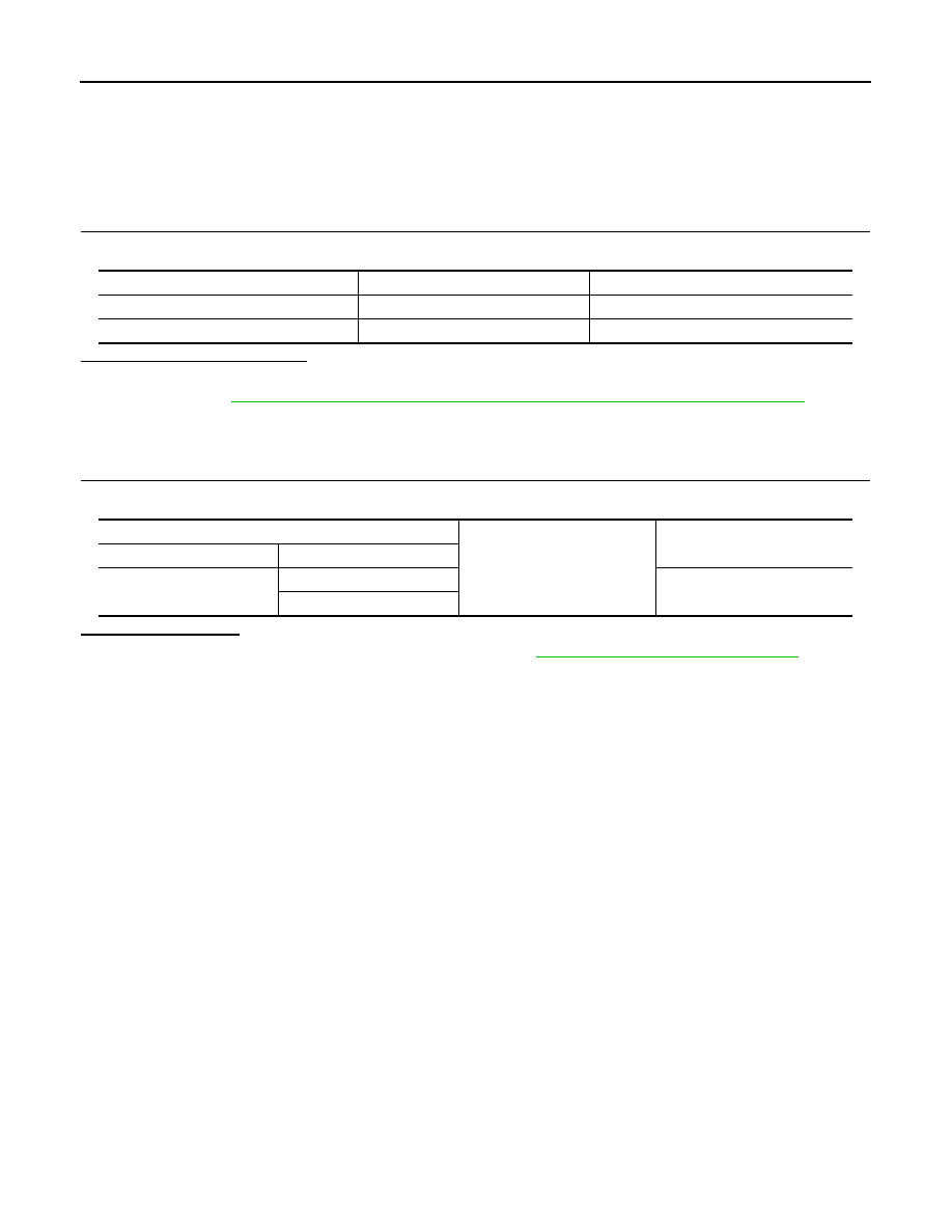
Monitor item

Condition

Status

DESTINATION

NAM

HAZARD

ON

Automatic back door control unit

Ground

Continuity

Connector

Terminal

B8

21

Existed

22

INTEGRATED HOMELINK TRANSMITTER

DLK-165

< DTC/CIRCUIT DIAGNOSIS >

[WITH INTELLIGENT KEY SYSTEM]

C

D

E

F

G

H

I

J

L

M

A

B

DLK

N

O

P

INTEGRATED HOMELINK TRANSMITTER

Description

INFOID:0000000005517667

Integrated Homelink Transmitter can store and transmit a maximum of 3 radio signals.
Allows operation of garage doors, gates, home and office lighting, entry door locks and security system, etc.
Integrated Homelink Transmitter power supply uses vehicle battery, which enables it to maintain every pro-
gram in case battery is discharged or removed.

Component Function Check

INFOID:0000000005517668

1.

CHECK FUNCTION

Check that system receiver (garage door opener, etc.) operates with original hand-held transmitter.

Is the inspection result normal?

YES

>> GO TO 2.

NO

>> Receiver or hand-held transmitter is malfunctioning.

2.

CHECK ILLUMINATE

1.

Turn ignition switch OFF.

2.

Does red light of transmitter illuminate when any transmitter button is pressed?

Is the inspection result normal?

YES

>> GO TO 3.

NO

>> Refer to 

DLK-165, "Diagnosis Procedure"

.

3.

CHECK TRANSMITTER

Check transmitter with Tool*.
*:For details, refer to Technical Service Bulletin.

Is the inspection result normal?

YES

>> Receiver or hand-held transmitter malfunction, not vehicle related.

NO

>> Replace auto anti-dazzling inside mirror (homelink universal transceiver). Refer to 

MIR-70,

"Removal and Installation"

 (with ADP) or 

MIR-93, "Removal and Installation"

 (Without ADP).

Diagnosis Procedure

INFOID:0000000005517669

1.

CHECK POWER SUPPLY

1.

Turn ignition switch OFF.

2.

Disconnect auto anti-dazzling inside mirror (homelink universal transceiver) connector.

3.

Check voltage between auto anti-dazzling inside mirror (home link universal transceiver) harness connec-
tor and ground.

Is the inspection result normal?

YES

>> GO TO 2.

NO

>>

Check the following.

• 10A fuse [No. 3 located in the fuse block (J/B)]
• 10A fuse [No. 6 located in the fuse block (J/B)]
• Harness for open or short between fuse and auto anti-dazzling inside mirror (homelink universal

transceiver).

2.

CHECK GROUND CIRCUIT

Auto anti-dazzling inside mirror

(Homelink universal transceiver) 

Condition

Voltage (V)

(Approx.)

Connector

Terminal

R9

10

Ground

Ignition switch position: 
OFF

Battery voltage

6

Ignition switch position: 
ON

DLK-166

< DTC/CIRCUIT DIAGNOSIS >

[WITH INTELLIGENT KEY SYSTEM]

INTEGRATED HOMELINK TRANSMITTER

Check continuity between auto anti-dazzling inside mirror (homelink universal transceiver) harness connector
and ground.

Is the inspection result normal?

YES

>> GO TO 3.

NO

>> Repair harness.

3.

CHECK INTERMITTENT INCIDENT

Refer to 

GI-39, "Intermittent Incident"

.

>> INSPECTION END

Auto anti-dazzling inside mirror

(Homelink universal transceiver)

Ground

Continuity 

Connector

Terminal

R9

8

Existed

POWER DOOR LOCK SYSTEM

DLK-167

< DTC/CIRCUIT DIAGNOSIS >

[WITH INTELLIGENT KEY SYSTEM]

C

D

E

F

G

H

I

J

L

M

A

B

DLK

N

O

P

POWER DOOR LOCK SYSTEM

Wiring Diagram - POWER DOOR LOCK SYSTEM -

INFOID:0000000005517670

JCKWM2155GB


содержание   ..  412  413  414  415   ..