Nissan Murano Z51. Manual - part 413


  Главная      Nissan     Nissan Murano Z51 (2010 year) - Service Manual


поиск по сайту            


содержание   ..  411  412  413  414   ..


Nissan Murano Z51. Manual - part 413


DLK-160

< DTC/CIRCUIT DIAGNOSIS >

[WITH INTELLIGENT KEY SYSTEM]

AUTOMATIC BACK DOOR MOTOR

AUTOMATIC BACK DOOR MOTOR

Description

INFOID:0000000005517659

The automatic back door motor is integrated in the automatic back door unit. The automatic back door motor
opens/closes the back door. 

Diagnosis Procedure

INFOID:0000000005517660

1.

CHECK AUTOMATIC BACK DOOR MOTOR CIRCUIT

1.

Turn ignition switch OFF.

2.

Disconnect automatic back door control unit connector and automatic back door unit connector.

3.

Check continuity between automatic back door control unit harness connector and automatic back door
unit harness connector.

4.

Check continuity between automatic back door control unit harness connector and ground.

Is the inspection result normal?

YES

>> GO TO 2.

NO

>> Repair or replace harness.

2.

CHECK AUTOMATIC BACK DOOR CONTROL UNIT OUTPUT

1.

Connect automatic back door control unit connector and automatic back door motor connector.

2.

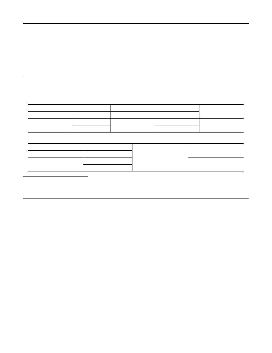
Check voltage between automatic back door unit and ground.

Automatic back door control unit

Automatic back door unit

Continuity

 Connector

Terminal 

 Connector

Terminal 

B7

27

B76

7

Existed

29

8

Automatic back door control unit

Ground

Continuity

 Connector

Terminal 

B7

27

Not existed

29

AUTOMATIC BACK DOOR MOTOR

DLK-161

< DTC/CIRCUIT DIAGNOSIS >

[WITH INTELLIGENT KEY SYSTEM]

C

D

E

F

G

H

I

J

L

M

A

B

DLK

N

O

P

Is the inspection result normal?

YES

>> Replace automatic back door unit. Refer to 

DLK-354, "POWER BACK DOOR DRIVE ASSEMBLY

: Removal and Installation"

.

NO

>> Replace automatic back door control unit. Refer to 

DLK-370, "Removal and Installation"

.

Terminals

Condition

Voltage (V)

(Approx.)

(+)

(–)

 Automatic back door 

control unit connector

Terminal 

B76

7

Ground

Automatic back 
door

Active (open)

Battery voltage

Active (close)

Other than above

0

8

Ground

Automatic back 
door

Active (close)

Battery voltage

Active (open)

Other than above

0

JMKIA1865ZZ

JMKIA1865ZZ

DLK-162

< DTC/CIRCUIT DIAGNOSIS >

[WITH INTELLIGENT KEY SYSTEM]

BACK DOOR CLOSURE MOTOR

BACK DOOR CLOSURE MOTOR

Description

INFOID:0000000005517661

The back door lock assembly consists of the open switch, close switch, half latch switch and closure motor.
The automatic back door control unit determines the back door lock condition according to the signal from
each switch and performs the open/close operation of closure motor.

Diagnosis Procedure

INFOID:0000000005517662

1.

CHECK BACK DOOR CLOSURE MOTOR CIRCUIT

1.

Turn ignition switch OFF.

2.

Disconnect automatic back door control unit connector and back door lock assembly connector.

3.

Check continuity between automatic back door control unit harness connector and back door lock assem-
bly harness connector. 

4.

Check continuity between automatic back door control unit harness connector and ground.

Is the inspection result normal?

YES

>> GO TO 2.

NO

>> Repair or replace harness.

2.

CHECK BACK DOOR CLOSURE MOTOR CIRCUIT

1.

Connect automatic back door control unit connector and back door lock assembly connector.

2.

Check voltage between automatic back door unit harness connector and ground. 

Is the inspection result normal?

YES

>> Replace back door lock assembly. Refer to 

DLK-353, "DOOR LOCK : Removal and Installation"

.

NO

>> Replace automatic back door control unit. Refer to 

DLK-370, "Removal and Installation"

.

Automatic back door control unit

Back door lock assembly

Continuity 

 Connector

Terminal

 Connector

Terminal

B8

11

D179

1

Not existed

2

Existed

12

1

Existed

2

Not existed

Automatic back door control unit

Ground

Continuity 

 Connector

Terminal

B8

11

Not existed

12

(+)

(–)

Condition

Voltage (V)

(Approx.) 

Automatic back door control unit

 Connector

Terminal

B8

11

Ground

Back door closure

Close operation

Battery voltage

Other than above

0

12

Open operation

Battery voltage

Other than above

0

AUTOMATIC BACK DOOR WARNING BUZZER

DLK-163

< DTC/CIRCUIT DIAGNOSIS >

[WITH INTELLIGENT KEY SYSTEM]

C

D

E

F

G

H

I

J

L

M

A

B

DLK

N

O

P

AUTOMATIC BACK DOOR WARNING BUZZER

Description

INFOID:0000000005517663

Performs operation method guide and warning with buzzer.

Diagnosis Procedure

INFOID:0000000005517664

1.

CHECK AUTOMATIC BACK DOOR WARNING BUZZER POWER SUPPLY CIRCUIT

1.

Turn ignition switch OFF.

2.

Disconnect automatic back door warning buzzer connector.

3.

Check voltage between automatic back door warning buzzer harness connector and ground.

Is the inspection result normal?

YES

>> GO TO 2.

NO

>> Repair or replace harness.

2.

CHECK AUTOMATIC BACK DOOR WARNING BUZZER OUTPUT SIGNAL CIRCUIT

1.

Disconnect automatic back door control unit connector.

2.

Check continuity between automatic back door control unit harness connector and automatic back door
warning buzzer harness connector.

3.

Check continuity between automatic back door control unit harness connector and ground.

Is the inspection result normal?

YES

>> Replace automatic back door warning buzzer. Refer to 

DLK-371, "Removal and Installation"

.

NO

>> Repair or replace harness.

(+)

(–)

Voltage (V)

(Approx.) 

Automatic back door warning buzzer

 Connector

Terminal

B27

1

Ground

Battery voltage

Automatic back door control unit

 Automatic back door warning buzzer

Continuity 

Connector

Terminal

Connector

Terminal

B8

1

B27

2

Existed

Automatic back door control unit

Ground

Continuity 

Connector

Terminal

B8

1

Not existed


содержание   ..  411  412  413  414   ..