содержание .. 300 301 302 303 ..
Nissan Murano Z51. Manual - part 302
DIAGNOSIS SYSTEM [ABS ACTUATOR AND ELECTRIC UNIT (CONTROL
UNIT)]
BRC-31
< SYSTEM DESCRIPTION >
[VDC/TCS/ABS]
C
D
E
G
H
I
J
K
L
M
A
B
BRC
N
O
P
NOTE:
A brief moment of On/Off condition occurs every 20 seconds after ignition switch turned ON. This is not malfunction because it is a oper-
ation for checking.
ACTIVE TEST MODE
CAUTION:
• Never perform active test while driving vehicle.
• Make sure to completely bleed air from brake system.
• The active test cannot be started when ABS warning lamp, VDC OFF indicator lamp, SLIP indicator
lamp and brake warning lamp is ON.
• ABS warning lamp, VDC OFF indicator lamp, SLIP indicator lamp and brake warning lamp are ON
during active test.
NOTE:
• When active test is performed while depressing the pedal, the pedal depression amount will change. This is
normal. (Only solenoid valve and ABS motor.)
• “TEST IS STOPPED” in “ABS” with CONSULT-III is displayed 10 seconds after operation start.
• After “TEST IS STOPPED” in “ABS” with CONSULT-III is displayed, to perform test again.
Test Item
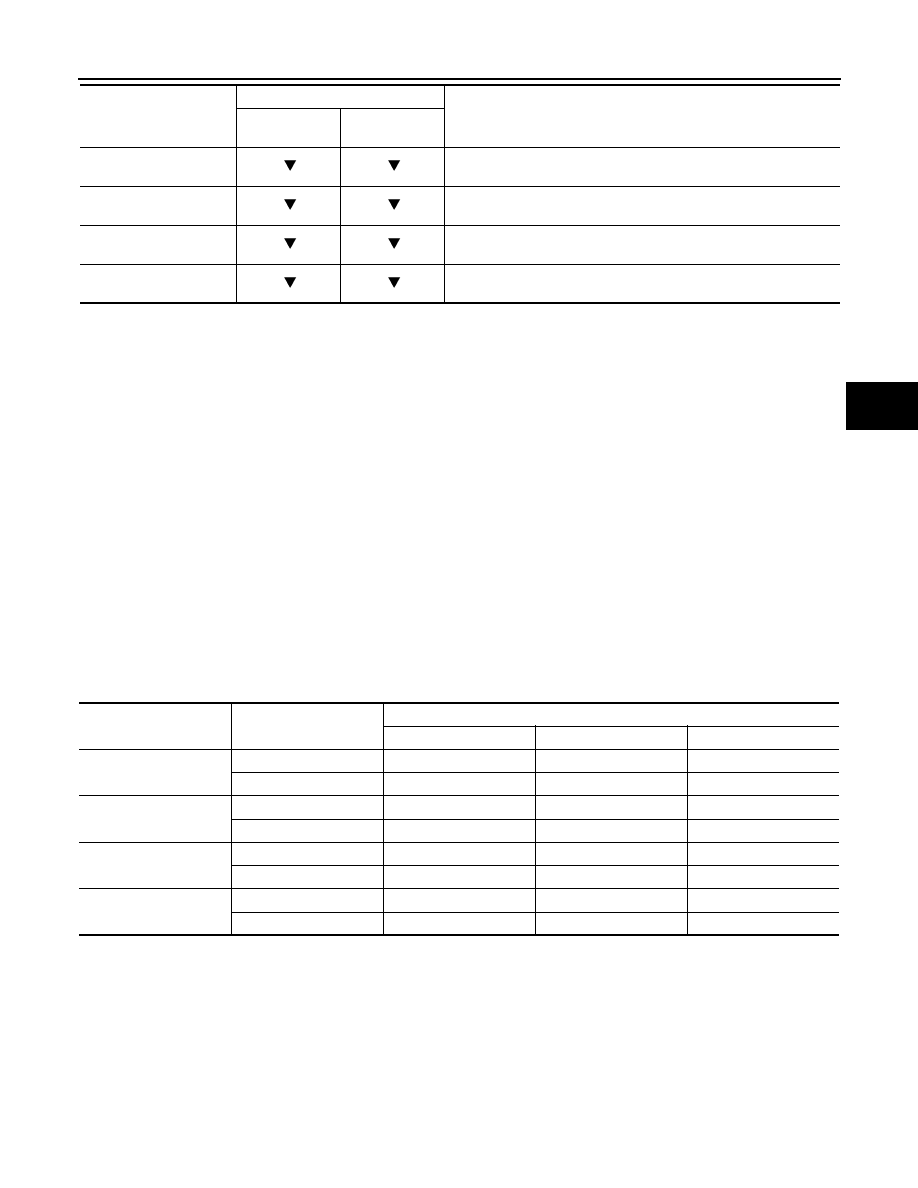
ABS SOLENOID VALVE
• Select “Up”, “Keep” and “Down” of “ACTIVE TEST” in “ABS” with CONSULT-III. Then use screen monitor to
check that solenoid valve operates as shown in the table below.
*: On for 1 to 2 seconds after the select, and then Off.
NOTE:
A brief moment of On/Off condition occurs every 20 seconds after ignition switch turned ON. This is not malfunction because it is a
operation for checking.
ABS SOLENOID VALVE (ACT)
• Select “Up”, “ACT UP” and “ACT KEEP” of “ACTIVE TEST” in “ABS” with CONSULT-III. Then use screen
monitor to check that solenoid valve operates as shown in the table below.
EBD WARN LAMP
(On/Off)
Brake warning lamp
CRANKING SIG
(On/Off)
Crank operation
4WD FAIL REQ
(On/Off)
AWD fail-safe signal status
2WD/4WD
(2WD/4WD)
Distinguish 2WD and AWD
Monitor item (Unit)
SELECT MONITOR ITEM
Remarks
ECU INPUT
SIGNALS
MAIN SIGNALS
Test item
Display item
Display
Up
Keep
Down
FR RH SOL
FR RH IN SOL
Off
On
On
FR RH OUT SOL
Off
Off
On*
FR LH SOL
FR LH IN SOL
Off
On
On
FR LH OUT SOL
Off
Off
On*
RR RH SOL
RR RH IN SOL
Off
On
On
RR RH OUT SOL
Off
Off
On*
RR LH SOL
RR LH IN SOL
Off
On
On
RR LH OUT SOL
Off
Off
On*