Nissan Murano Z51. Manual - part 260


  Главная      Nissan     Nissan Murano Z51 (2010 year) - Service Manual


поиск по сайту            


содержание   ..  258  259  260  261   ..


Nissan Murano Z51. Manual - part 260


BCS

BODY CONTROL SYSTEM

BCS-7

< SYSTEM DESCRIPTION >

C

D

E

F

G

H

I

J

K

L

B

A

O

P

N

SYSTEM DESCRIPTION

BODY CONTROL SYSTEM

System Description

INFOID:0000000005518265

OUTLINE

• BCM (Body Control Module) controls the various electrical components. It inputs the information required to

the control from CAN communication and the signal received from each switch and sensor. 

• BCM has combination switch reading function for reading the operation status of combination switches (light,

turn signal, wiper and washer) in addition to a function for controlling the operation of various electrical com-
ponents. It also has the signal transmission function as the passed point of signal and the power saving con-
trol function that reduces the power consumption with the ignition switch OFF.

• BCM is equipped with the diagnosis function that performs the diagnosis with CONSULT-III and various set-

tings.

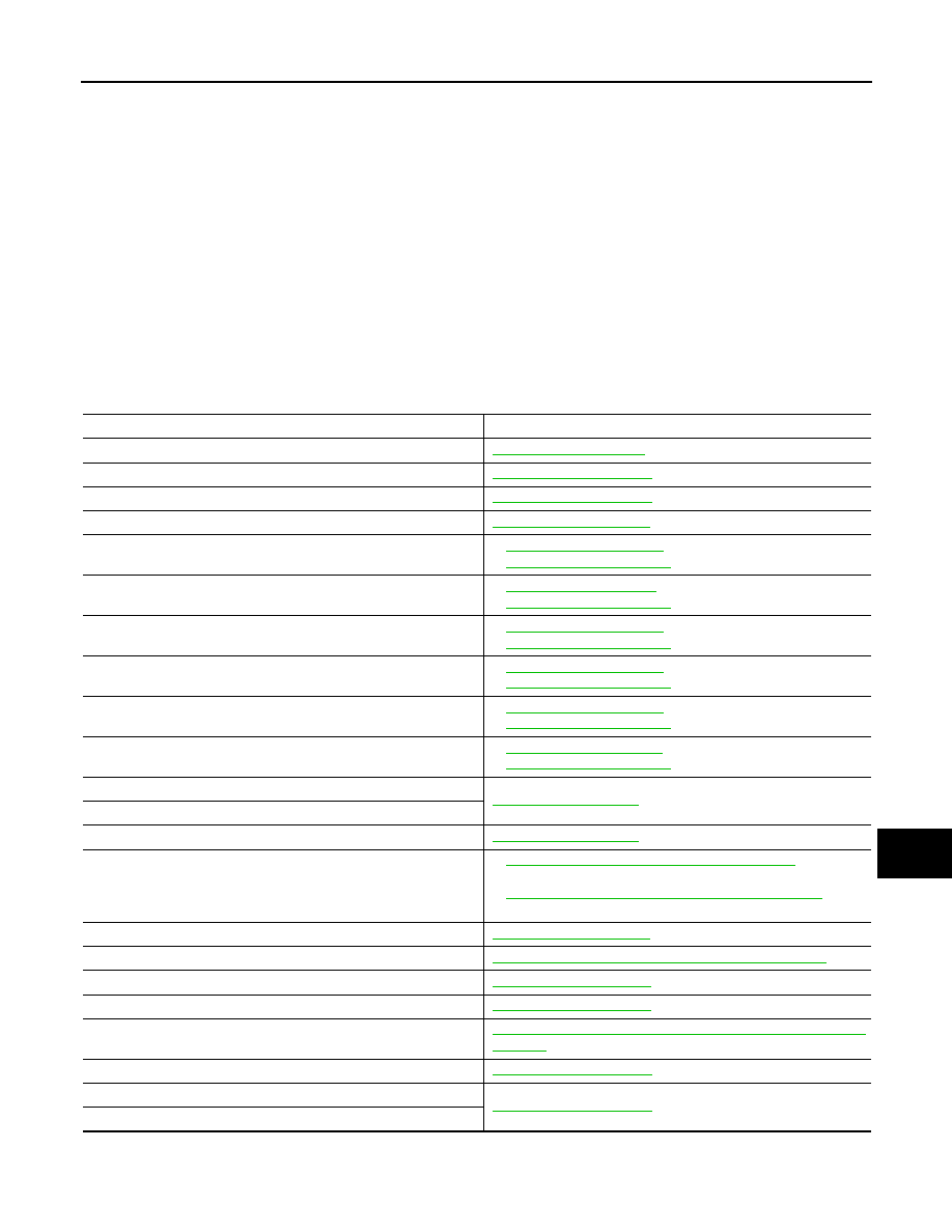
BCM CONTROL FUNCTION LIST

System

Reference

Combination switch reading system

BCS-9, "System Diagram"

Signal buffer system

BCS-13, "System Diagram"

Power consumption control system

BCS-14, "System Diagram"

Auto light system

EXL-13, "System Diagram"

Turn signal and hazard warning lamp system

EXL-17, "System Diagram"

 (Xenon type headlamp)

EXL-205, "System Diagram"

 (Halogen type headlamp)

Headlamp system

EXL-8, "System Diagram"

 (Xenon type headlamp)

EXL-197, "System Diagram"

 (Halogen type headlamp)

Parking, license plate and tail lamps system

EXL-19, "System Diagram"

 (Xenon type headlamp)

EXL-207, "System Diagram"

 (Halogen type headlamp)

Front fog lamp system

EXL-15, "System Diagram"

 (Xenon type headlamp)

EXL-203, "System Diagram"

 (Halogen type headlamp)

Exterior lamp battery saver system

EXL-21, "System Diagram"

 (Xenon type headlamp)

EXL-209, "System Diagram"

 (Halogen type headlamp)

Daytime running light system

EXL-11, "System Diagram"

 (Xenon type headlamp)

EXL-199, "System Diagram"

 (Halogen type headlamp)

Interior room lamp control system

INL-5, "System Diagram"

Step lamp system

Interior room lamp battery saver system

INL-8, "System Diagram"

Front wiper and washer system

WW-5, "WITH RAIN SENSOR : System Diagram"

 (With rain 

sensor)

WW-9, "WITHOUT RAIN SENSOR : System Diagram"

 (With-

out rain sensor)

Rear wiper and washer system

WW-14, "System Diagram"

Warning chime system

WCS-5, "WARNING CHIME SYSTEM : System Diagram"

Door lock system

DLK-14, "System Diagram"

Automatic back door system

DLK-44, "System Diagram"

Automatic drive positioner system

ADP-13, "AUTOMATIC DRIVE POSITIONER SYSTEM : System 
Diagram"

Nissan Vehicle Immobilizer System (NVIS) - NATS

SEC-15, "System Diagram"

Vehicle security system

SEC-20, "System Diagram"

Panic alarm

BCS-8

< SYSTEM DESCRIPTION >

BODY CONTROL SYSTEM

Component Parts Location

INFOID:0000000005518266

Rear window defogger system

DEF-4, "WITH BOSE SYSTEM : System Diagram"

 (With 

BOSE system)

DEF-6, "WITHOUT BOSE SYSTEM : System Diagram"

 (With-

out BOSE system)

Intelligent Key system/engine start system

DLK-18, "INTELLIGENT KEY SYSTEM : System Diagram"

Power window system

PWC-7, "System Diagram"

Retained accessory power (RAP) system

PWC-7, "System Description"

Tire pressure monitor system (TPMS) - AIR PRESSURE MONI-
TOR

WT-8, "TIRE PRESSURE MONITORING SYSTEM : System Di-
agram"

System

Reference

1.

BCM

A.

Behind of combination meter

JPMIA0897ZZ

BCS

COMBINATION SWITCH READING SYSTEM

BCS-9

< SYSTEM DESCRIPTION >

C

D

E

F

G

H

I

J

K

L

B

A

O

P

N

COMBINATION SWITCH READING SYSTEM

System Diagram

INFOID:0000000005681334

NOTE:
• *1: TAIL LAMP switch links lighting switch 1ST position.
• *2: “FR WIP INT/AT” is FR WIPER INT/AUTO.

System Description

INFOID:0000000005681335

OUTLINE

• BCM reads the status of the combination switch (light, turn signal, wiper and washer) and recognizes the

status of each switch.

• BCM is a combination of 5 output terminals (OUTPUT 1 - 5) and 5 input terminals (INPUT 1 - 5). It reads a

maximum of 20 switch status.

COMBINATION SWITCH MATRIX

Combination switch circuit

NOTE:
• *1: TAIL LAMP switch links lighting switch 1ST position.
• *2: “FR WIP INT/AT” is FR WIPER INT/AUTO.

JMMIA0292GB

JMMIA0293GB

BCS-10

< SYSTEM DESCRIPTION >

COMBINATION SWITCH READING SYSTEM

Combination switch INPUT-OUTPUT system list

NOTE:

Headlamp has a dual system switch.

COMBINATION SWITCH READING FUNCTION

Description

• BCM reads the status of the combination switch at 10 ms interval normally.

NOTE:
BCM reads the status of the combination switch at 60 ms interval when BCM is controlled at low power con-
sumption mode.

• BCM operates as follows and judges the status of the combination switch.
- INPUT 1 - 5 outputs the voltage waveforms of 5 systems simultaneously.
- It operates the transistor on OUTPUT side in the following order: OUTPUT 5 

 4 

 3 

 2 

 1.

- The voltage waveform of INPUT corresponding to the formed circuit changes according to the operation of

the transistor on OUTPUT side if any (1 or more) switches are ON.

- It reads this change of the voltage as the status signal of the combination switch.

System

OUTPUT 1

OUTPUT 2

OUTPUT 3

OUTPUT 4

OUTPUT 5

INPUT 1

FR WASHER

FR WIPER LOW

TURN LH

TURN RH

INPUT 2

FR WIPER HI

FR WIPER INT/

AUTO

PASSING

HEADLAMP 1

INPUT 3

WIP VOLUME 1

HEADLAMP 2

HI BEAM

INPUT 4

WIP VOLUME 3

AUTO LIGHT

TAIL LAMP

INPUT 5

WIP VOLUME 2

FR FOG

JPMIA0067GB

JPMIA0068GB


содержание   ..  258  259  260  261   ..