содержание .. 1453 1454 1455 1456 ..
Nissan Murano Z51. Manual - part 1455
DIFFERENTIAL SIDE OIL SEAL
TM-171
< REMOVAL AND INSTALLATION >
[CVT: RE0F09B]
C
E
F
G
H
I
J
K
L
M
A
B
TM
N
O
P
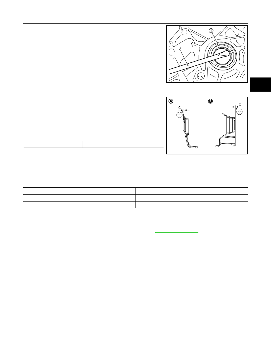
5.
Remove differential side oil seal (1) and side oil seal (transfer
joint) using a flat-bladed screwdriver (A).
CAUTION:
Be careful not to scratch transaxle case and converter
housing.
INSTALLATION
Note the following, and install in the reverse order of removal.
• Drive each differential side oil seal and side oil seal (transfer joint)
evenly using a commercial service tool so that differential side oil
seal and side oil seal (transfer joint) protrudes by the dimension
(C) respectively.
Unit: mm (in)
NOTE:
Differential side oil seal and side oil seal (transfer joint) pulling direc-
tion is used as the reference.
CAUTION:
• Never reuse differential side oil seals and side oil seal (transfer joint).
• Apply CVT fluid to differential side oil seals and side oil seal (transfer joint).
Drift to be used:
AWD : Inspection
INFOID:0000000005514123
INSPECTION AFTER INSTALLATION
Check for CVT fluid leakage and check CVT fluid level. Refer to
JPDIA0118ZZ
A
: Transaxle case side
B
: Converter housing side
Dimension C
0
±
0.5 (0
±
0.020)
JPDIA0619ZZ
Location
Tool number (Kent-Moore No.)
Differential side oil seal
ST33400001 (J-26082)
Side oil seal (transfer joint)
KV40100621 (J-25405)