Nissan Murano Z51. Manual - part 1448


  Главная      Nissan     Nissan Murano Z51 (2010 year) - Service Manual


поиск по сайту            


содержание   ..  1446  1447  1448  1449   ..


Nissan Murano Z51. Manual - part 1448


PRECAUTIONS

TM-143

< PRECAUTION >

[CVT: RE0F09B]

C

E

F

G

H

I

J

K

L

M

A

B

TM

N

O

P

FOR MEXICO : Precaution

INFOID:0000000005593808

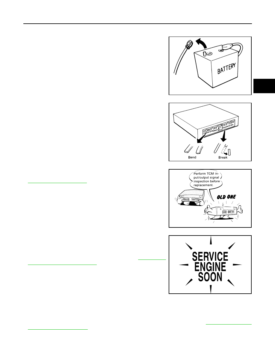
• Turn ignition switch OFF and disconnect negative battery

cable before connecting or disconnecting the TCM harness
connector. Because battery voltage is applied to TCM even if
ignition switch is turned OFF.

• When connecting or disconnecting pin connectors into or

from TCM, do not damage pin terminals (bend or break).
Check that there are not any bends or breaks on TCM pin ter-
minal, when connecting pin connectors.

• Perform TCM input/output signal inspection and check

whether TCM functions normally or not before replacing TCM.

TM-111, "Reference Value"

.

• Perform “DTC Confirmation Procedure” after performing each

TROUBLE DIAGNOSIS.
If the repair is completed the DTC should not be displayed in
the “DTC Confirmation Procedure”.

• Always use the specified brand of CVT fluid. Refer to 

MA-16, "FOR

MEXICO : Fluids and Lubricants"

.

• Use lint-free paper, not cloth rags, during work.
• Dispose of the waste oil using the methods prescribed by law, ordi-

nance, etc. after replacing the CVT fluid.

FOR MEXICO : Service Notice or Precaution

INFOID:0000000005593809

OBD-II SELF-DIAGNOSIS

• CVT self-diagnosis is performed by the TCM in combination with the ECM. The results can be read through

the blinking pattern of the Malfunction Indicator Lamp (MIL). Refer to the table on 

TM-36, "CONSULT-III

Function (TRANSMISSION)"

 for the indicator used to display each self diagnostic results.

• The self diagnostic results indicated by the MIL are automatically stored in both the ECM and TCM memo-

ries.

SEF289H

SEF291H

MEF040DA

SEF217U

TM-144

< PRECAUTION >

[CVT: RE0F09B]

PRECAUTIONS

Always perform the procedure on 

TM-34, "Diagnosis Description"

 to complete the repair and avoid

unnecessary blinking of the MIL.

For details of OBD-II, refer to 

EC-102, "Diagnosis Description"

.

• Certain systems and components, especially those related to OBD, may use the new style slide-lock-

ing type harness connector. For description and how to disconnect, refer to 

PG-108

.

FOR MEXICO : ATFTEMP COUNT Conversion Table 

INFOID:0000000005593810

ATFTEMP COUNT

Temperature 

°

C (

°

F)

ATFTEMP COUNT

Temperature 

°

C (

°

F)

4

–30 (–22)

177

90 (194)

8

–20 (–4)

183

95 (203)

13

–10 (14)

190

100 (212)

17

–5 (23)

196

105 (221)

21

0 (32)

201

110 (230)

27

5 (41)

206

115 (239)

32

10 (50)

210

120 (248)

39

15 (59)

214

125 (257)

47

20 (68)

218

130 (266)

55

25 (77)

221

135 (275)

64

30 (86)

224

140 (284)

73

35 (95)

227

145 (293)

83

40 (104)

229

150 (302)

93

45 (113)

231

155 (311)

104

50 (122)

233

160 (320)

114

55 (131)

235

165 (329)

124

60 (140)

236

170 (338)

134

65 (149)

238

175 (347)

143

70 (158)

239

180 (356)

152

75 (167)

241

190 (374)

161

80 (176)

243

200 (392)

169

85 (185)

PREPARATION

TM-145

< PREPARATION >

[CVT: RE0F09B]

C

E

F

G

H

I

J

K

L

M

A

B

TM

N

O

P

PREPARATION

PREPARATION

Special Service Tools

INFOID:0000000005514091

The actual shapes of Kent-Moore tools may differ from those of special service tools illustrated here.

Commercial Service Tools

INFOID:0000000005514092

Tool number
(Kent-Moore No.)
Tool name

Description


(OTC3492)
Oil pressure gauge set

Measuring line pressure

ST33400001
(J-26082)
Drift
a: 60 mm (2.36 in) dia.
b: 47 mm (1.85 in) dia.

Installing differential side oil seal

KV40100621
(J-25405)
Drift
a: 76 mm (2.99 in) dia.
b: 69 mm (2.72 in) dia.

Installing side oil seal (transfer joint)

SCIA7531E

ZZA0814D

ZZA0814D

Tool number
Tool name

Description

Power tool

Loosening nuts and bolts

31197CA000
Drive plate location guide
a: 14 mm (0.55 in) dia.

Installing transaxle assembly

PBIC0190E

SCIA2013E

TM-146

< PERIODIC MAINTENANCE >

[CVT: RE0F09B]

CVT FLUID

PERIODIC MAINTENANCE

CVT FLUID

Inspection

INFOID:0000000005514093

CHECKING CVT FLUID

The fluid level should be checked with the fluid warmed up to 50 to 80

°

C (122 to 176

°

F). The fluid level check

procedure is as follows:
1.

Check for fluid leakage.

2.

With the engine warmed up, drive the vehicle in an urban area.
When ambient temperature is 20

°

C (68

°

F), it takes about 10

minutes for the CVT fluid to warm up to 50 to 80

°

C (122 to

176

°

F).

3.

Park the vehicle on a level surface.

4.

Apply parking brake firmly.

5.

With engine at idle, while depressing brake pedal, move shift
selector throughout the entire shift range.

6.

Pull out the CVT fluid level gauge from the CVT fluid charging
pipe after pressing the tab on the CVT fluid level gauge to
release the lock.

7.

Wipe fluid off the CVT fluid level gauge. Insert the CVT fluid
level gauge rotating 180

°

 from the originally installed position,

then securely push the CVT fluid level gauge until it meets the
top end of the CVT fluid charging pipe.

CAUTION:

When wiping away the CVT fluid level gauge, always use
lint-free paper, not a cloth rag.

8.

Place the selector lever in “P” or “N” and check that the fluid
level is within the specified range.

CAUTION:

When reinstalling CVT fluid level gauge, insert it into the
CVT fluid charging pipe and rotate it to the original installa-
tion position until securely locked.

CVT FLUID CONDITION

SMA146B

SCIA1933E

SCIA1931E

SCIA1932E


содержание   ..  1446  1447  1448  1449   ..