содержание .. 1401 1402 1403 1404 ..
Nissan Murano Z51. Manual - part 1403
EPS SYSTEM
STC-3
< SYSTEM DESCRIPTION >
C
D
E
F
H
I
J
K
L
M
A
B
STC
N
O
P
SYSTEM DESCRIPTION
EPS SYSTEM
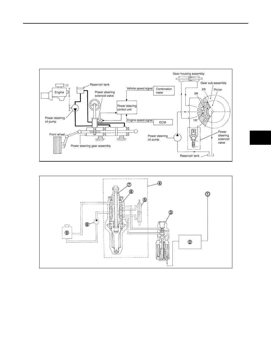
System Diagram
INFOID:0000000005515240
CONTROL DIAGRAM
CROSS-SECTIONAL VIEW
System Description
INFOID:0000000005515241
• The EPS system controls the power steering solenoid valve through the power steering control unit.
JSGIA0119GB
1.
Combination meter
2.
Power steering control unit
3.
Power steering solenoid valve
4.
Steering gear assembly
5.
Gear housing assembly
6.
Gear sub-assembly
7.
Pinion
8.
Power steering oil pump
9.
Reservoir tank
JSGIA0376ZZ