Nissan Murano Z51. Manual - part 1402


  Главная      Nissan     Nissan Murano Z51 (2010 year) - Service Manual


поиск по сайту            


содержание   ..  1400  1401  1402  1403   ..


Nissan Murano Z51. Manual - part 1402


ST-46

< SERVICE DATA AND SPECIFICATIONS (SDS) 

SERVICE DATA AND SPECIFICATIONS (SDS)

SERVICE DATA AND SPECIFICATIONS (SDS)

SERVICE DATA AND SPECIFICATIONS (SDS)

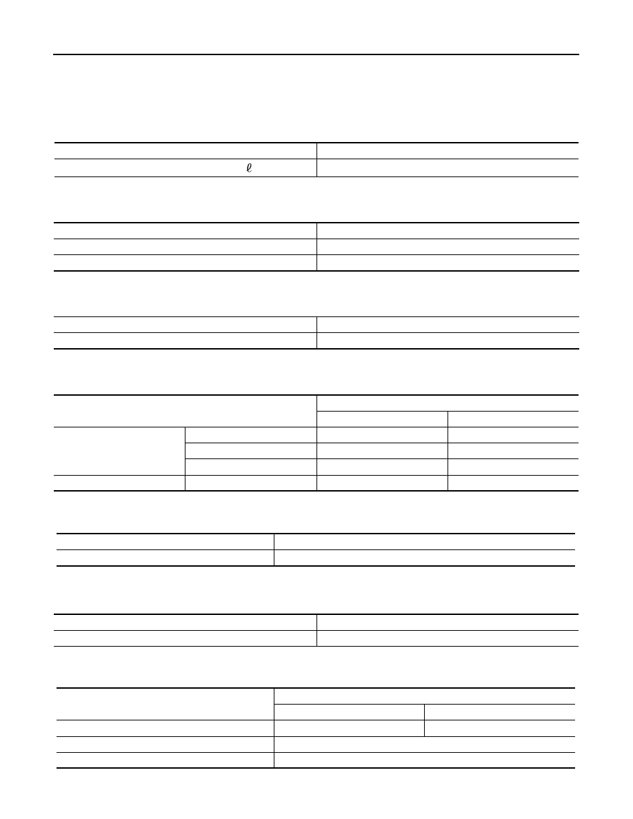
General Specifications

INFOID:0000000005514493

Steering Wheel Axial End Play and Play

INFOID:0000000005514494

Unit: mm (in)

Steering Wheel Turning Force

INFOID:0000000005514495

Unit: N·m (kg-m, in-lb)

Steering Angle

INFOID:0000000005514496

Unit: Degree minute (Decimal degree)

Steering Column Length

INFOID:0000000005514497

Unit: mm (in)

Steering Column Mounting Dimensions

INFOID:0000000005514498

Unit: mm (in)

Steering Column Operating Range

INFOID:0000000005514499

Steering gear model

PR26AF

Fluid capacity (Approx.)

 (US qt, lmp qt)

1.0 (1-1/8, 7/8)

Item

Standard

Steering wheel axial end play

0 (0)

Steering wheel play on the outer circumference

0 – 35 (0 – 1.38)

Item

Standard

Steering wheel turning force

7.45 (0.76, 66)

Item

Standard

Wheel size: 18 inch

Wheel size: 20 inch

Inner wheel

Minimum

33

°

30

 (33.5

°

)

32

°

00

 (32.0

°

)

Nominal

36

°

30

 (36.5

°

)

35

°

00

 (35.0

°

)

Maximum

37

°

30

 (37.5

°

)

36

°′

 (36.0

°

)

Outer wheel

Nominal

31

°

30

 (31.5

°

)

30

°

30

 (30.5

°

)

Item

Standard

Column length

463 (18.23)

Item

Standard

Mounting dimension

30 (1.18) or less

Item

Standard

Without electric motor

With electric motor

Tilt operating range 

15

°

18

°

Telescopic operating range 

40 mm (1.57 in)

Rotating torque

0.49 N·m (0.05 kg-m, 4 in-lb)

SERVICE DATA AND SPECIFICATIONS (SDS)

ST-47

< SERVICE DATA AND SPECIFICATIONS (SDS) 

C

D

E

F

H

I

J

K

L

M

A

B

ST

N

O

P

Lower Shaft Length

INFOID:0000000005514500

Unit: mm (in)

Rack Sliding Force

INFOID:0000000005514501

Unit: N (kg, lb)

Rack Stroke

INFOID:0000000005514502

Unit: mm (in)

Socket Swing Force and Rotating Torque

INFOID:0000000005514503

SWING FORCE

Unit: N (kg, lb)

ROTATING TORQUE

Unit: N·m (kg-m, in-lb)

Socket Axial End Play

INFOID:0000000005514504

Unit: mm (in)

Inner Socket Length

INFOID:0000000005514505

Unit: mm (in)

Relief Oil Pressure

INFOID:0000000005514506

Unit: kPa (kg/cm

2

, psi)

Item

Standard

Lower shaft length

160 (6.3) or more

Item

Standard

2WD

AWD

Rack sliding force

195 – 258 (19.9 – 26.3, 43.8 – 

57.9)

227 – 305 (23.2 – 31.1, 51.1 – 

68.5)

Item

Standard

Wheel size: 18 inch

Wheel size: 20 inch

Rack neutral position 

70.5 (2.776)

68.0 (2.677)

Item

Standard

Outer socket

4.81 – 45.7 (0.5 – 4.6, 1.1 – 10.2)

Inner socket

8.9 – 64 (0.91 – 6.5, 2.01 – 14.3)

Item

Standard

Outer socket 

0.3 – 2.9 (0.03 – 0.29, 3 – 25)

Item

Standard

Outer socket

0.5 (0.02) or less

Inner socket

0.2 (0.008) or less

Item

Standard

Rack neutral position

120.3 (4.74)

Item

Standard

Relief oil pressure

9,500 – 10,300 (96.9 – 105.1, 1,378 – 1,494)

STC-1

STEERING

C

D

E

F

H

I

J

K

L

M

SECTION 

STC

A

B

STC

N

O

P

CONTENTS

STEERING CONTROL SYSTEM

BASIC INSPECTION  ....................................

2

DIAGNOSIS AND REPAIR WORK FLOW  .........

2

Work Flow  .................................................................

2

SYSTEM DESCRIPTION  ..............................

3

EPS SYSTEM  ......................................................

3

System Diagram ........................................................

3

System Description  ...................................................

3

Component Parts Location ........................................

5

Component Description .............................................

5

DTC/CIRCUIT DIAGNOSIS  ..........................

6

POWER SUPPLY AND GROUND CIRCUIT .......

6

Description ................................................................

6

Diagnosis Procedure .................................................

6

POWER STEERING SOLENOID VALVE  ...........

7

Description ................................................................

7

Diagnosis Procedure .................................................

7

Component Inspection  ..............................................

8

ENGINE SPEED SIGNAL CIRCUIT  ....................

9

Description ................................................................

9

Diagnosis Procedure .................................................

9

VEHICLE SPEED SIGNAL CIRCUIT  .................

11

Description ..............................................................

11

Diagnosis Procedure ...............................................

11

ECU DIAGNOSIS INFORMATION ..............

13

POWER STEERING CONTROL UNIT  ...............

13

Reference Value  .....................................................

13

Wiring Diagram - ELECTRONICALLY CON-
TROLLED POWER STEERING SYSTEM -  ............

14

Fail-Safe ..................................................................

16

SYMPTOM DIAGNOSIS  ..............................

18

UNBALANCE STEERING WHEEL TURNING 
FORCE (TORQUE VARIATION) .......................

18

Description ...............................................................

18

Diagnosis Procedure  ...............................................

18

PRECAUTION ..............................................

19

PRECAUTIONS .................................................

19

FOR USA AND CANADA  ..........................................

19

FOR USA AND CANADA : Precaution for Supple-
mental Restraint System (SRS) "AIR BAG" and 
"SEAT BELT PRE-TENSIONER" ............................

19

FOR USA AND CANADA : Precaution Necessary 
for Steering Wheel Rotation after Battery Discon-
nect ..........................................................................

19

FOR MEXICO .............................................................

20

FOR MEXICO : Precaution for Supplemental Re-
straint System (SRS) "AIR BAG" and "SEAT BELT 
PRE-TENSIONER" ..................................................

20

FOR MEXICO : Precaution Necessary for Steer-
ing Wheel Rotation after Battery Disconnect ...........

20

REMOVAL AND INSTALLATION  ...............

21

POWER STEERING CONTROL UNIT ..............

21

Removal and Installation  .........................................

21

STC-2

< BASIC INSPECTION >

DIAGNOSIS AND REPAIR WORK FLOW

BASIC INSPECTION

DIAGNOSIS AND REPAIR WORK FLOW

Work Flow

INFOID:0000000005515239

DETAILED FLOW

1.

COLLECT THE INFORMATION FROM THE CUSTOMER

It is also important to clarify customer complaints before inspection. First of all, reproduce symptoms and
understand them fully. Ask customer about his/her complaints carefully. In some cases, it is necessary to
check symptoms by driving vehicle with customer.

CAUTION:

Customers are not professional. It is dangerous to make an easy guess like “maybe the customer
means that...,” or “maybe the customer mentions this symptom”.

>> GO TO 2.

2.

CHECK THE STATUS

1.

Power steering fluid leakage and check the power steering fluid level. Refer to 

ST-12, "Inspection"

.

2.

Check the drive belt tension. Refer to 

EM-17, "Checking"

.

3.

Check the power steering gear for damages, cracks and fluid leakage. Refer to 

ST-36, "Inspection"

.

4.

Check the relief oil pressure. Refer to 

ST-42, "Inspection"

.

>> GO TO 3.

3.

DIAGNOSIS CHART BY SYMPTOM

Perform the diagnosis by symptom. Refer to 

STC-18, "Diagnosis Procedure"

.

>> GO TO 4.

4.

FINAL CHECK

Check the input/output standard values for the power steering control unit.
Are the power steering control unit input/output values within standard ranges respectively?

YES

>> INSPECTION END

NO

>> GO TO 2.


содержание   ..  1400  1401  1402  1403   ..