Nissan Murano Z51. Manual - part 1395


  Главная      Nissan     Nissan Murano Z51 (2010 year) - Service Manual


поиск по сайту            


содержание   ..  1393  1394  1395  1396   ..


Nissan Murano Z51. Manual - part 1395


ST-18

< REMOVAL AND INSTALLATION >

STEERING COLUMN

STEERING COLUMN

WITHOUT ELECTRIC MOTOR

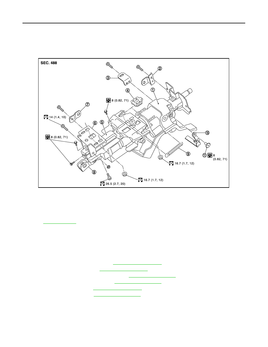
WITHOUT ELECTRIC MOTOR : Exploded View

INFOID:0000000005514474

WITHOUT ELECTRIC MOTOR : Removal and Installation

INFOID:0000000005514475

REMOVAL

1.

Set the vehicle to the straight-ahead position.

2.

Place the tilt to the highest level. Place the telescopic to the longest level.

3.

Remove driver air bag module. Refer to 

SR-11, "Exploded View"

.

4.

Remove steering wheel. Refer to 

ST-17, "Exploded View"

.

5.

Remove instrument driver lower panel. Refer to 

IP-12, "Exploded View"

.

6.

Remove steering column cover. Refer to 

IP-12, "Exploded View"

.

7.

Remove spiral cable. Refer to 

SR-11, "Exploded View"

.

8.

Remove cluster lid A. Refer to 

IP-12, "Exploded View"

.

1.

Steering column assembly

2.

Bracket

3.

Bracket

4.

Slide plate

5.

Slide bracket

6.

Lower mount bracket

7.

Bracket

8.

Upper joint

9.

Spring

10. Tilt lever

11.

Clip

Refer to 

GI-4, "Components"

 for symbols in the figure.

JSGIA0610GB

STEERING COLUMN

ST-19

< REMOVAL AND INSTALLATION >

C

D

E

F

H

I

J

K

L

M

A

B

ST

N

O

P

9.

Remove knee protector (1).

10. Disconnect each switch harness connectors installed to steering

column assembly.

11. Remove the joint mounting bolt and nut (lower shaft side), and

separate the joint from lower shaft.

12. Remove steering column assembly.

CAUTION:

• Never give axial impact to steering column assembly dur-

ing removal.

• Never move steering gear assembly when removing steering column assembly.

INSTALLATION

Note the following, and install in the reverse order of removal.
• Install the slide plate (1) and steering column housing (2) so that

the mounting dimensions (L) is within the specified range as
described below.           

• Tighten the mounting bolts in the order shown in the figure when

installing the steering column assembly.

• Be careful of the following points when installing the steering col-

umn assembly.

CAUTION:

• Never give axial impact to steering column assembly during

installation.

• Never move steering gear assembly.
• Never reuse the joint mounting nut (lower shaft side).

• Adjust neutral position of steering angle sensor. Refer to 

BRC-9,

"ADJUSTMENT OF STEERING ANGLE SENSOR NEUTRAL
POSITION : Special Repair Requirement"

.

WITHOUT ELECTRIC MOTOR : Inspection

INFOID:0000000005514476

INSPECTION AFTER REMOVAL

• Check each part of steering column assembly for damage or other malfunctions. Replace if necessary.
• Measure steering column assembly rotating torque using a preload gauge [SST: ST3127S000 (J-25765-A)].

Replace steering column assembly if outside the standard.

: Bolt

JSGIA0306ZZ

Standard

L

: 2.0 mm (0.079 in) or less

JSGIA0315ZZ

JSGIA0310ZZ

Standard

Rotating torque

: Refer to 

ST-46, "Steering 

Column Operating 
Range"

.

ST-20

< REMOVAL AND INSTALLATION >

STEERING COLUMN

• Measure the length (L) as shown, if vehicle has been involved in a

minor collision. Replace steering column assembly if out side the
standard.

• Install the bracket (1) and steering column housing (2) so that the

clearance (A) is within the specified range as described below.
Replace steering column assembly if out side the standard.

INSPECTION AFTER INSTALLATION

• Check each part of steering column assembly for damage or other malfunctions. Replace if necessary.
• Check the steering wheel play, neutral position steering wheel, steering wheel turning force, and front wheel

turning angle. Refer to 

ST-14, "Inspection"

.

• Check tilt and telescopic mechanism operating range tilt operating

range (L), telescopic operating range (T) as shown in the figure.

WITH ELECTRIC MOTOR

Standard

L

: Refer to 

ST-46, "Steering 

Column Length"

.

JSGIA0562ZZ

Standard

A

: Refer to 

ST-46, "Steering 

Column Mounting Dimen-
sions"

.

JSGIA0389ZZ

Standard

T

:  Refer  to 

ST-46, "Steering 

Column Operating 
Range"

.

L

:  Refer  to 

ST-46, "Steering 

Column Operating 
Range"

.

JSGIA0307ZZ

STEERING COLUMN

ST-21

< REMOVAL AND INSTALLATION >

C

D

E

F

H

I

J

K

L

M

A

B

ST

N

O

P

WITH ELECTRIC MOTOR : Exploded View

INFOID:0000000005514477

WITH ELECTRIC MOTOR : Removal and Installation

INFOID:0000000005514478

REMOVAL

1.

Set the vehicle to the straight-ahead position.

2.

Place the tilt to the highest level. Place the telescopic to the longest level.

3.

Remove driver air bag module. Refer to 

SR-11, "Exploded View"

.

4.

Remove steering wheel. Refer to 

ST-17, "Exploded View"

.

5.

Remove instrument driver lower panel. Refer to 

IP-12, "Exploded View"

.

6.

Remove steering column cover. Refer to 

IP-12, "Exploded View"

.

7.

Remove spiral cable. Refer to 

SR-14, "Exploded View"

.

8.

Remove cluster lid A. Refer to 

IP-12, "Exploded View"

.

1.

Bracket

2.

Steering column assembly

3.

Bracket

4.

Clip

5.

Tilt motor

6.

Bracket

7.

Bracket

8.

Bracket

9.

Slide bracket

10. Lower mount bracket

11.

Upper joint

12. Bracket

13. Telescopic motor

14. Bracket

15. Bracket

Refer to 

GI-4, "Components"

 for symbols in the figure.

JSGIA0529GB


содержание   ..  1393  1394  1395  1396   ..