содержание .. 1297 1298 1299 1300 ..
Nissan Murano Z51. Manual - part 1299
CRASH ZONE SENSOR
SR-21
< REMOVAL AND INSTALLATION >
[FOR USA AND CANADA]
C
D
E
F
G
I
J
K
L
M
A
B
SR
N
O
P
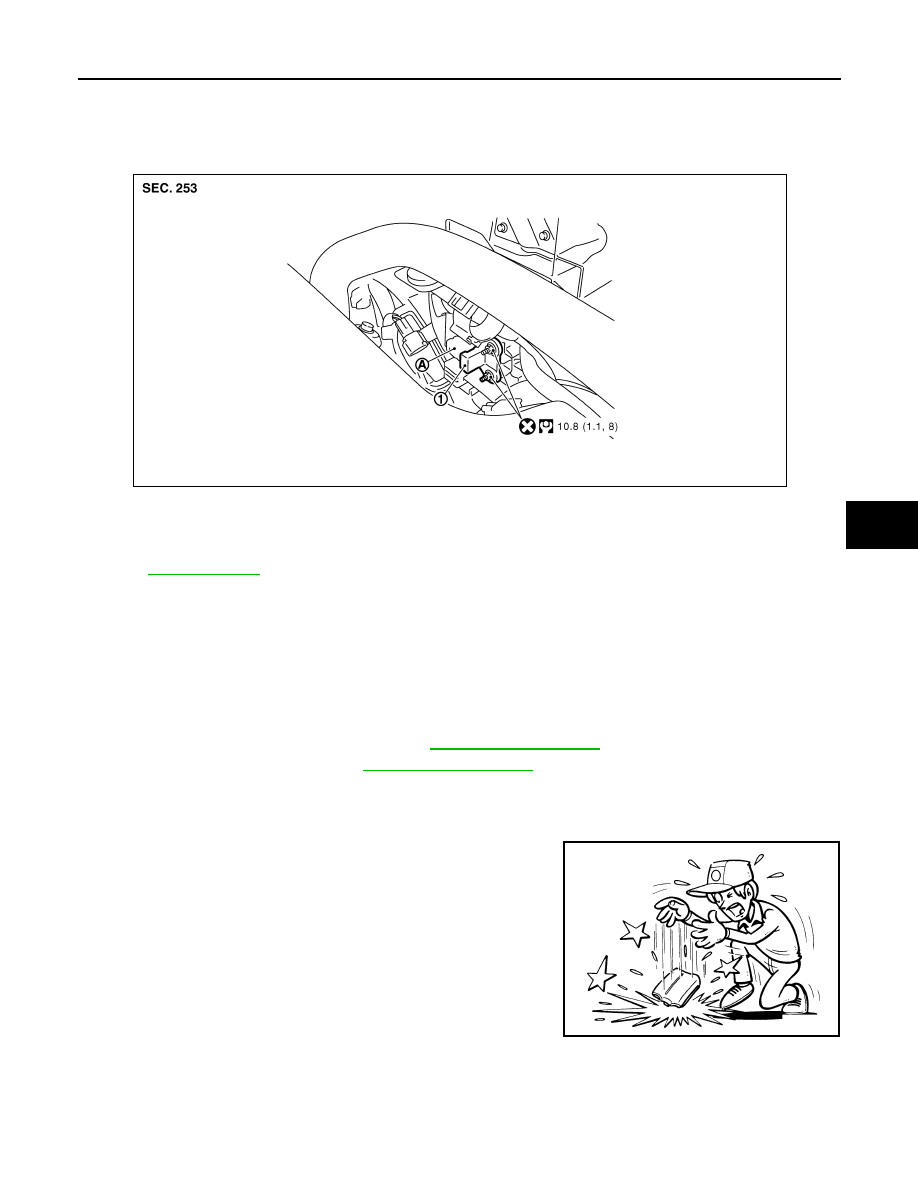
CRASH ZONE SENSOR
Exploded View
INFOID:0000000005518911
Removal and Installation
INFOID:0000000005518912
WARNING:
• Before servicing, turn ignition switch OFF, disconnect battery negative terminal and wait 3 minutes
or more.
• Never use air tools or electric tools for servicing.
REMOVAL
1.
Remove the radiator cover grill (RH). Refer to
2.
Remove the air duct (inlet). Refer to
3.
Remove the crash zone sensor fixing nuts.
4.
Disconnect the crash zone sensor harness connector, and then remove the crash zone sensor.
CAUTION:
• Never impact the crash zone sensor.
• Replace the crash zone sensor if it has been dropped or sus-
tained an impact.
• Replace the crash zone sensor of deployed SRS driver air bag and deployed SRS front passenger air
bag.
INSTALLATION
Install in the reverse order of removal.
1.
Crash zone sensor
A.
Crash zone sensor harness connec-
tor
Refer to
for symbols in the figure.
JMHIA0515GB
JMHIA0009ZZ