содержание .. 1074 1075 1076 1077 ..
Nissan Murano Z51. Manual - part 1076
PCS-46
< SYSTEM DESCRIPTION >
[POWER DISTRIBUTION SYSTEM]
DIAGNOSIS SYSTEM (BCM)
*: OFF is displayed when brake pedal is depressed while brake switch power supply is OFF.
ACTIVE TEST
PRMT RKE STRT
NOTE:
This item is displayed, but cannot be monitored.
KEY SW -SLOT
Indicates [ON/OFF] condition of key slot.
TRNK/HAT MNTR
NOTE:
This item is displayed, but cannot be monitored.
RKE-LOCK
Indicates [ON/OFF] condition of LOCK signal from Intelligent Key.
RKE-UNLOCK
Indicates [ON/OFF] condition of UNLOCK signal from Intelligent Key.
RKE-TR/BD
NOTE:
This item is displayed, but cannot be monitored.
RKE-PANIC
Indicates [ON/OFF] condition of PANIC button of Intelligent Key.
RKE-P/W OPEN
Indicates [ON/OFF] condition of P/W DOWN signal from Intelligent Key.
RKE-MODE CHG
Indicates [ON/OFF] condition of MODE CHANGE signal from Intelligent Key.
RKE OPE COUN1
When remote keyless entry receiver receives the signal transmitted while operating on Intelligent Key, the
numerical value start changing.
RKE OPE COUN2
NOTE:
This item is displayed, but cannot be monitored.
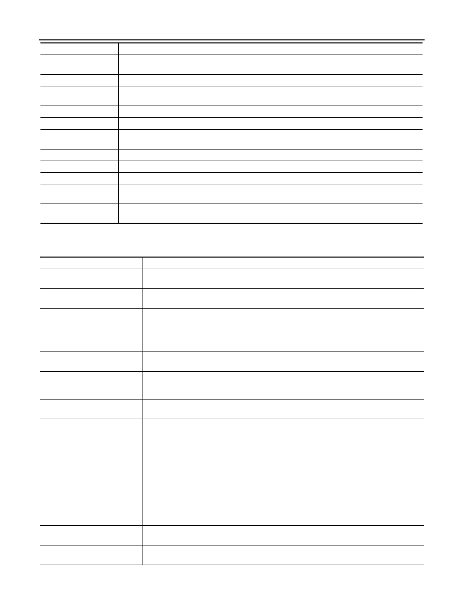
Monitor Item
Condition
Test item
Description
BATTERY SAVER
This test is able to check interior room lamp operation.
The interior room lamp will be activated after “ON” on CONSULT-III screen is touched.
PW REMOTO DOWN SET
This test is able to check power window down operation.
The power window down will be activated after “ON” on CONSULT-III screen is touched.
INSIDE BUZZER
This test is able to check warning chime in combination meter operation.
• Take away warning chime sounds when “TAKE OUT” on CONSULT-III screen is touched.
• Key warning chime sounds when “KEY WARN” on CONSULT-III screen is touched.
• P position warning chime sounds when “P RNG WARN” on CONSULT-III screen is touched.
• ACC warning chime sounds when “ACC WARN” on CONSULT-III screen is touched.
OUTSIDE BUZZER
This test is able to check Intelligent Key warning buzzer operation.
The Intelligent Key warning buzzer will be activated after “ON” on CONSULT-III screen is touched.
INDICATOR
This test is able to check warning lamp operation.
• “KEY” Warning lamp illuminates when “KEY ON” on CONSULT-III screen is touched.
• “KEY” Warning lamp flashes when “KEY IND” on CONSULT-III screen is touched.
INT LAMP
This test is able to check interior room lamp operation.
The interior room lamp will be activated after “ON” on CONSULT-III screen is touched.
LCD
This test is able to check meter display information
• Engine start information displays when “BP N” on CONSULT-III screen is touched.
• Engine start information displays when “BP I” on CONSULT-III screen is touched.
• Key ID warning displays when “ID NG” on CONSULT-III screen is touched.
• Steering lock information displays when “ROTAT” on CONSULT-III screen is touched.
NOTE:
For models without steering lock unit, “ROTAT” is displayed, but cannot be tested.
• P position warning displays when “SFT P” on CONSULT-III screen is touched.
• Intelligent Key insert information displays when “INSRT” on CONSULT-III screen is touched.
• Intelligent Key low battery warning displays when “BATT” on CONSULT-III screen is touched.
• Take away through window warning displays when “NO KY” on CONSULT-III screen is touched.
• Take away warning display when “OUTKEY” on CONSULT-III screen is touched.
• OFF position warning display when “LK WN” on CONSULT-III screen is touched.
TRUNK/GLASS HATCH
This test is able to check back door opener actuator open operation.
This actuator opens when “ON” on CONSULT-III screen is touched.
FLASHER
This test is able to check hazard warning lamp operation.
The hazard warning lamps will be activated after “ON” on CONSULT-III screen is touched.