Nissan Murano Z51. Manual - part 1043


  Главная      Nissan     Nissan Murano Z51 (2010 year) - Service Manual


поиск по сайту            


содержание   ..  1041  1042  1043  1044   ..


Nissan Murano Z51. Manual - part 1043


MWI-30

< SYSTEM DESCRIPTION >

METER SYSTEM

INFORMATION DISPLAY : Component Description

INFOID:0000000005524851

1.

Fuel level sensor unit (sub)

2.

ABS actuator and electric unit (con-
trol unit)

3.

Oil pressure switch

4.

TCM

5.

Ambient sensor

6.

ECM

7.

IPDM E/R

8.

BCM

9.

Combination meter

10.

Fuel level sensor unit and fuel pump 
(main)

A.

Lower right side of rear seat

B.

Engine room (RH)

C.

Engine front side

D.

Engine room (LH)

E.

Front bumper (left back)

F.

Engine room (LH)

G.

Engine room (LH)

H.

Behind the combination meter

I.

Lower left side of rear seat
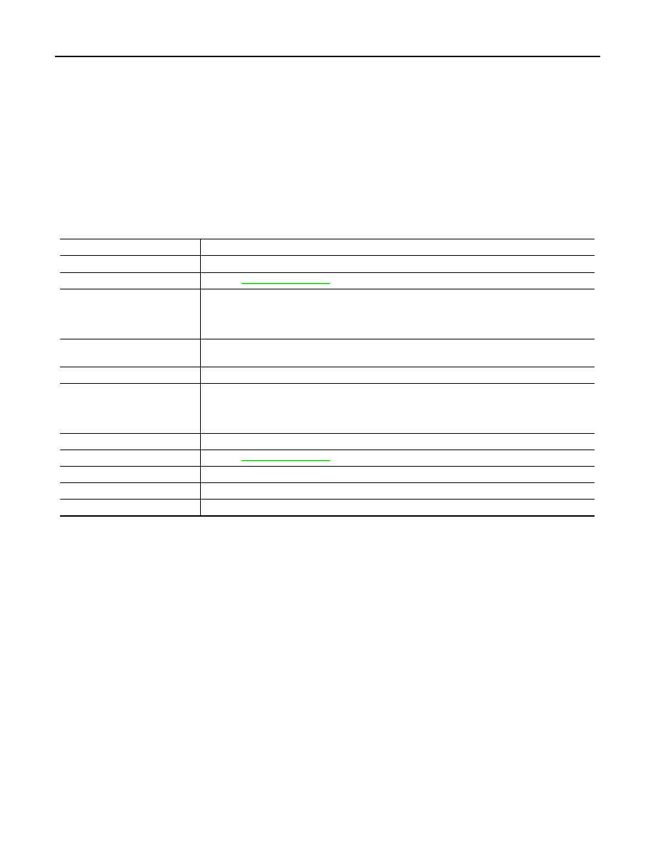
Unit

Description

Combination meter

Controls the information display according to the signal received from each unit.

Fuel level sensor unit

Refer to 

MWI-45, "Description"

.

ECM

Transmits the following signals to the combination meter via CAN communication.

• Engine speed signal

• Fuel consumption monitor signal

ABS actuator and electric unit 
(control unit)

Transmits the vehicle speed signal to the combination meter via CAN communication.

BCM

Transmits signals provided by various units to the combination meter via CAN communication.

Meter control switch

Transmits the following signals to the combination meter.

• Enter switch signal

• Select switch signal

Washer level switch

Transmits the washer level signal to the combination meter.

Parking brake switch

Refer to 

MWI-53, "Description"

.

Door switch

Transmits the door switch signals to BCM.

IPDM E/R

Transmits the ambient sensor signal to the combination meter.

Ambient sensor

Detects the ambient air temperature and transmits the ambient sensor signal to the IPDM E/R.

MWI

COMPASS

MWI-31

< SYSTEM DESCRIPTION >

C

D

E

F

G

H

I

J

K

L

M

B

A

O

P

COMPASS

Description

INFOID:0000000005524852

DESCRIPTION

• This electronic compass is able to display 8 primary directions: N, NE, E, SE, S, SW, W, NW.
• The compass switch (1) is used to operate the compass.

Switch Operation

• All standard compasses determine direction relative to magnetic north, however, this electronic compass is

designed to display direction relative to true north.

• The difference between magnetic north and true north varies from place to place across the surface of the

earth.

• This electronic compass must be “told” approximately where it is on the earth’s surface so that the magnetic

north reading can be properly converted into a true north display.

• To tell the electronic compass where it’s at, the earth is separated into numbered “Zone Variances”. The

zone variance number in which the compass is to function must be entered into this electronic compass.

• Each zone is magnetically about 4.2

°

 wide. Typically, anything under a 22.5

°

 total zone change is not noticed

on the electronic compass display. However, if a change over 22.5

°

 occurs, a reading may be off by one or

more primary directions.

• On long trips, the vehicle may leave its original zone and enter one or more new zones. Generally, you do

not need to reset the compass zone if you travel between 3 or 4 zones, such as business travel or vacation.
The typical driver will not notice any difference on the display within 3 or 4 zones. However, if the vehicle is
“permanently” moved to a new location, it is recommended that the compass zone be reset.

ZONE VARIATION SETTING PROCEDURE

1.

Press and hold the compass switch for 3 – 9 seconds.

2.

The current zone setting appears on the compass display.

3.

Find the current geographical location number in the zone varia-
tion chart.

4.

Select the new zone number. (Press the compass switch until
the new zone number appears on the compass display.)

5.

After select the new zone number, the compass display will
automatically shows a direction within a few seconds.

6.

Perform the following calibration procedure for more accurate
indications.

Press

Compass is turned ON/OFF

Press and hold
(for 3- 9 sec.)

Compass display (2) turns to zone variation change 
mode

Press and hold (for more 
than 9 sec.)

Compass display turns to calibration mode

SKIB8868E

SEL168Y

MWI-32

< SYSTEM DESCRIPTION >

COMPASS

CALIBRATION PROCEDURE

NOTE:
The compass calibrates itself under normal driving conditions. However, occasional circumstances may cause
the compass to operate inaccurately. Example: Driving from rural (wide open) areas to crowded city areas, or
if an aftermarket (i.e., non original equipment) antenna with a magnetic base is attached to the vehicle. Cali-
brate the mirror compass if the display shows only one direction or a limited number of directions.
NOTE:
• If “magnetic hats” are used in the dealership for vehicle identification, remove the hat from the vehicle before

performing the following steps. Do not put the hat back on the vehicle after the procedure is completed.

• Drive the vehicle to an open level area; away from large metallic objects, structures, and overhead power

lines.

• Turn off “non-essential” electrical accessories (rear window defrost, heater/air conditioning, wipers) and

close the doors.

1.

Verify the correct compass zone setting for the geographical location.

2.

Press and hold the compass switch for more than 9 seconds.

3.

“C” is displayed on the compass display when calibration starts.

4.

Drive slowly [less than 8 km/h (5 MPH)] in a circle until the “C / CAL” is replaced with primary headings (N,
NE, E, SE, S, SW, W, or NW).
NOTE:
This will require driving at least 2 complete 360 degree circles, 3 complete circles may be required.

5.

The compass calibration procedure is now complete. The compass should operate normally.
NOTE:
If at any time the compass continually displays the incorrect direction or the reading is erratic or locked,
repeat the calibration procedure.

Component Parts Location

INFOID:0000000005524853

Special Repair Requirement

INFOID:0000000005524854

1.

PERFORM ZONE VARIATION SETTING

Perform the zone variation setting. Refer to 

MWI-31, "Description"

>> GO TO 2.

2.

PERFORM CALIBRATION

Perform the calibration. Refer to 

MWI-31, "Description"

.

>> Setting completion

1

: Compass switch

2

: Compass display

SKIB8868E

MWI

DIAGNOSIS SYSTEM (METER)

MWI-33

< SYSTEM DESCRIPTION >

C

D

E

F

G

H

I

J

K

L

M

B

A

O

P

DIAGNOSIS SYSTEM (METER)

Diagnosis Description

INFOID:0000000005524855

SELF-DIAGNOSIS MODE

• Information display LCD segment operation can be checked in self-diagnosis mode.
• Meters/gauges can be checked in self-diagnosis mode.

OPERATION PROCEDURE

1.

Turn ignition switch OFF.

2.

While pressing the trip reset switch (1), turn ignition switch ON.
NOTE:
If the diagnosis function is activated with “trip A” displayed, the
mileage on “trip A” is reset to “0000.0”. (The same way for “trip
B”.)

3.

Make sure that the trip meter displays “0000.0”.

4.

Press the trip reset switch at least 3 times. (Within 7 seconds
after the ignition switch is turned ON.)

5.

The unified meter control unit is turned to self-diagnosis mode.
• All the segments on the odo/trip meter and shift position indicator illuminate.
• The segment dots of the information display LCD (1) blink

alternately. 

• Engine coolant temperature gauge and fuel gauge return to

zero, simultaneously.

NOTE:
• Check combination meter power supply and ground circuit when the self-diagnosis mode of the combi-

nation meter does not start. Replace combination meter if abnormal.

• If any of the segments are not displayed, replace combination meter.

6.

Each meter activates by pressing the trip reset switch.

NOTE:

JPNIA0743ZZ

JPNIA0766ZZ

JPNIA0739ZZ


содержание   ..  1041  1042  1043  1044   ..