Nissan Murano Z51. Manual - part 1041


  Главная      Nissan     Nissan Murano Z51 (2010 year) - Service Manual


поиск по сайту            


содержание   ..  1039  1040  1041  1042   ..


Nissan Murano Z51. Manual - part 1041


MWI-22

< SYSTEM DESCRIPTION >

METER SYSTEM

SHIFT POSITION INDICATOR : Component Description

INFOID:0000000005524839

WARNING LAMPS/INDICATOR LAMPS

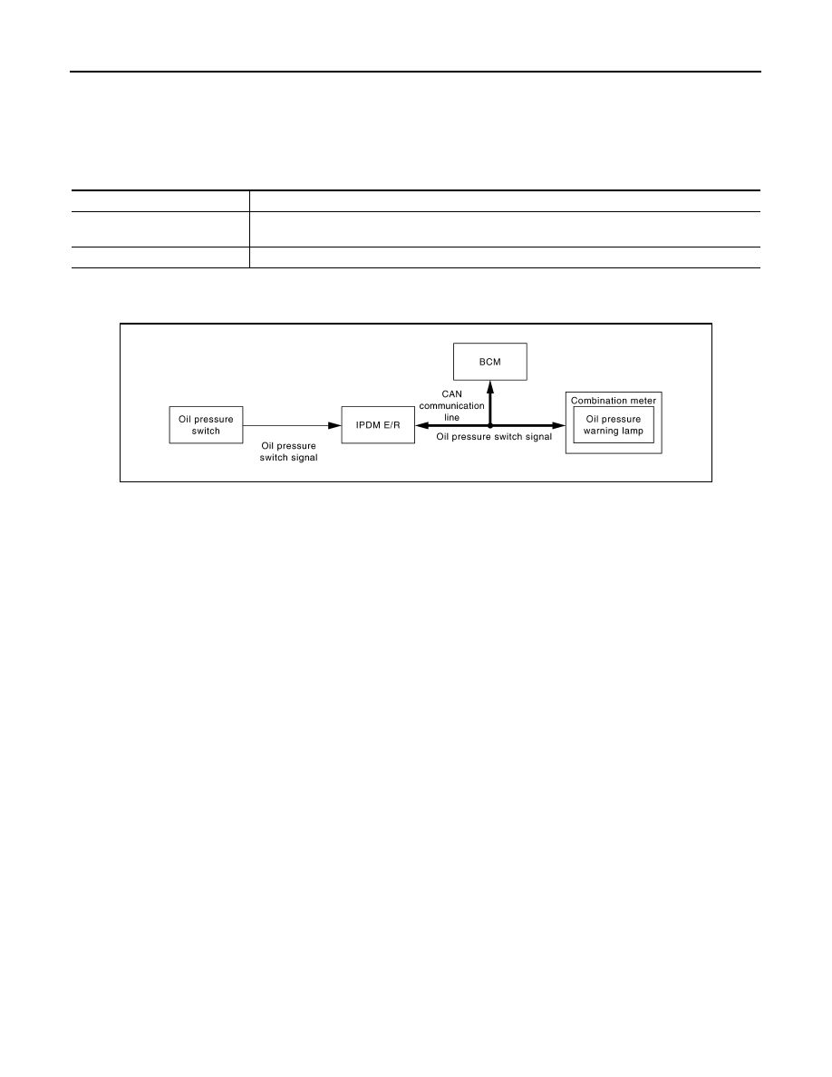
WARNING LAMPS/INDICATOR LAMPS : System Diagram

INFOID:0000000005524840

WARNING LAMPS/INDICATOR LAMPS : System Description

INFOID:0000000005524841

OIL PRESSURE WARNING LAMP

• IPDM E/R reads the ON/OFF signals from the oil pressure switch and transmits the oil pressure switch sig-

nal to the combination meter via BCM with the CAN communication line. 

• The combination meter turns the oil pressure warning lamp ON/OFF according to the oil pressure switch sig-

nal received via CAN communication. 

A.

Lower right side of rear seat

B.

Engine room (RH)

C.

Engine front side

D.

Engine room (LH)

E.

Front bumper (left back)

F.

Engine room (LH)

G.

Engine room (LH)

H.

Behind the combination meter

I.

Lower left side of rear seat

Unit

Description

Combination meter

Displays the shift position on the shift position indicator with shift position signal received from TCM 
via CAN communication.

TCM

Transmits shift position signal to the combination meter with CAN communication.

JSNIA0449GB

MWI

METER SYSTEM

MWI-23

< SYSTEM DESCRIPTION >

C

D

E

F

G

H

I

J

K

L

M

B

A

O

P

WARNING LAMPS/INDICATOR LAMPS : Component Parts Location

INFOID:0000000005524842

JPNIA0813ZZ

1.

Fuel level sensor unit (sub)

2.

ABS actuator and electric unit (con-
trol unit)

3.

Oil pressure switch

4.

TCM

5.

Ambient sensor

6.

ECM

7.

IPDM E/R

8.

BCM

9.

Combination meter

10.

Fuel level sensor unit and fuel pump 
(main)

MWI-24

< SYSTEM DESCRIPTION >

METER SYSTEM

WARNING LAMPS/INDICATOR LAMPS : Component Description

INFOID:0000000005524843

METER ILLUMINATION CONTROL

METER ILLUMINATION CONTROL : System Diagram

INFOID:0000000005524844

METER ILLUMINATION CONTROL : System Description

INFOID:0000000005524845

SYSTEM DESCRIPTION

The combination meter controls the meter illumination by the illumination control switch signal from the meter
control switch and the position light request signal transmitted by the BCM via CAN communication.

Daytime Mode

Meter illumination level can be adjusted in 22 steps using the illumi-
nation control switch (1) in daytime mode.

Nighttime Mode

• Combination meter changes the meter illumination to the nighttime mode by the position light request signal

from BCM via CAN communication.

• Meter illumination can be adjusted in 22 steps using the illumination control switch in nighttime mode.

Driver Welcome Function

Ring illumination gradually turns ON when a driver gets in the vehicle with intelligent key and closes the driver
side door.
NOTE:
Ring illumination gradually turns OFF when not turning the ignition switch ON at a certain period of time.

A.

Lower right side of rear seat

B.

Engine room (RH)

C.

Engine front side

D.

Engine room (LH)

E.

Front bumper (left back)

F.

Engine room (LH)

G.

Engine room (LH)

H.

Behind the combination meter

I.

Lower left side of rear seat

Unit

Description

Combination meter

Turns the oil pressure warning lamp ON/OFF according to the oil pressure switch signal received 
from BCM via CAN communication. 

IPDM E/R

Reads the ON/OFF signals from the oil pressure switch and transmits the oil pressure switch signal 
to the combination meter via BCM and CAN communication. 

Oil pressure switch

Refer to 

MWI-51, "Description"

BCM

Transmits the oil pressure switch signal received from IPDM E/R via CAN communication to the 
combination meter via CAN communication. 

JPNIA0746GB

JPNIA0742ZZ

MWI

METER SYSTEM

MWI-25

< SYSTEM DESCRIPTION >

C

D

E

F

G

H

I

J

K

L

M

B

A

O

P

Dial Effects Function

Combination meter detects the engine start when input engine speed signal at first. Pointers of speed meter
and tachometer sweep and ring illumination gradually turns ON when combination meter detects the engine
start. Then, combination meter starts the normal control.
NOTE:
• Engine coolant temperature gauge and fuel gauge do not function.
• Dial Effects Function can be turned ON/OFF from “SETTING” on the information display.

METER ILLUMINATION CONTROL : Component Parts Location

INFOID:0000000005524846

JPNIA0813ZZ


содержание   ..  1039  1040  1041  1042   ..