Murano Cross Cabriolet Z51 (2013 year). Manual - part 108
WW-12
< SYSTEM DESCRIPTION >
DIAGNOSIS SYSTEM (BCM)
*:Factory setting
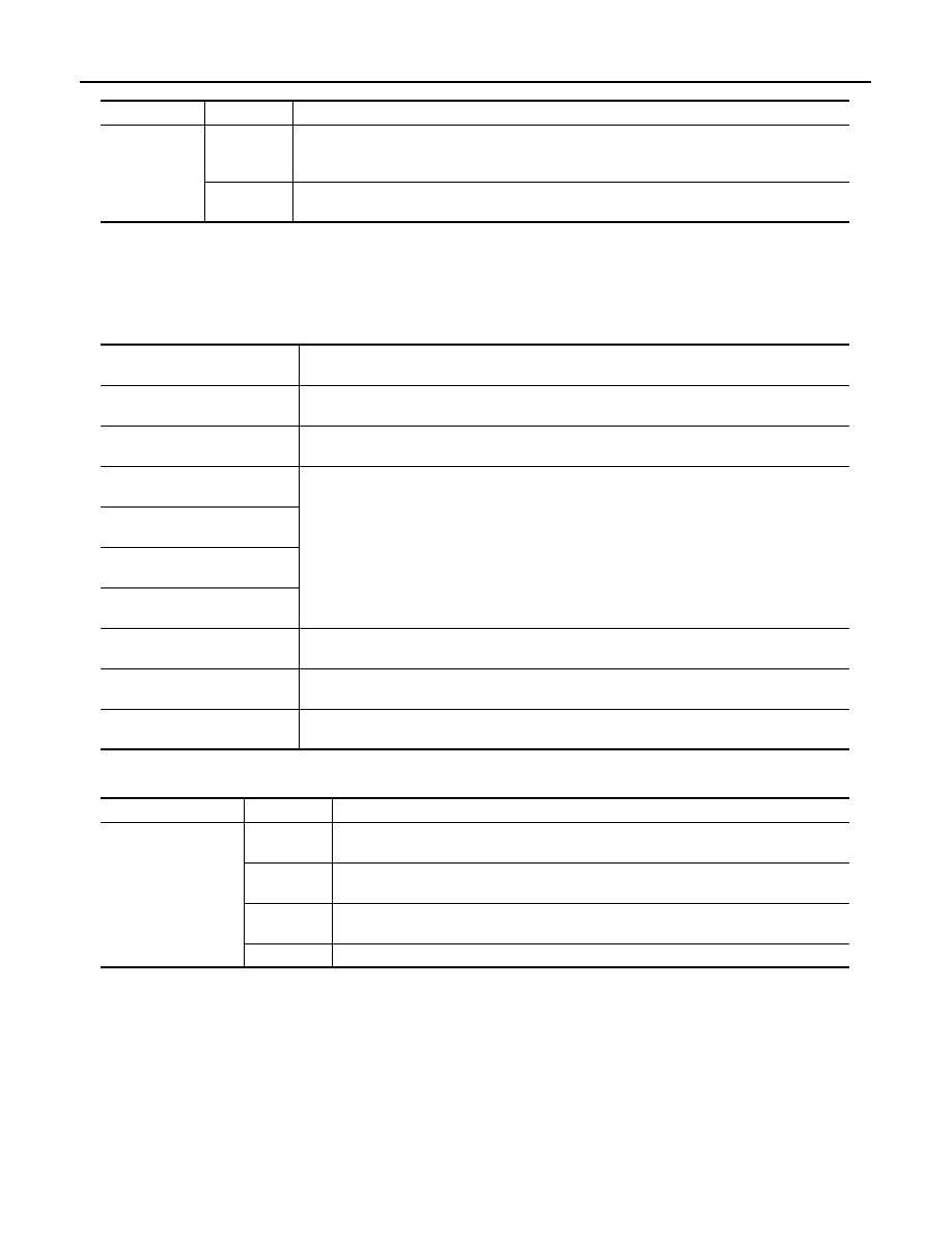
DATA MONITOR
NOTE:
The following table includes information (items) inapplicable to this vehicle. For information (items) applicable
to this vehicle, refer to CONSULT display items.
ACTIVE TEST
Service item
Setting item
Description
WIPER SPEED
SETTING
On
With vehicle speed
(Front wiper intermittent time linked with the vehicle speed and wiper intermittent dial position)
Off*
Without vehicle speed
(Front wiper intermittent time linked with the wiper intermittent dial position)
Monitor Item
[Unit]
Description
PUSH SW
[Off/On]
The switch status input from push-button ignition switch
VEH SPEED 1
[km/h]
Displays the value of the vehicle speed signal received from combination meter via CAN com-
munication
FR WIPER HI
[Off/On]
Status of each switch judged by BCM using the combination switch reading function
FR WIPER LOW
[Off/On]
FR WASHER SW
[Off/On]
FR WIPER INT
[Off/On]
FR WIPER STOP
[Off/On]
Displays the status of the front wiper stop position signal received from IPDM E/R via CAN
communication.
INT VOLUME
[1
−
7]
Status of each switch judged by BCM using the combination switch reading function
H/L WASH SW
[Off/On]
NOTE:
The item is indicated, but not monitored
Test item
Operation
Description
FR WIPER
Hi
Transmits the front wiper request signal (HI) to IPDM E/R via CAN communication to op-
erate the front wiper HI operation.
Lo
Transmits the front wiper request signal (LO) to IPDM E/R via CAN communication to
operate the front wiper LO operation.
INT
Transmits the front wiper request signal (INT) to IPDM E/R via CAN communication to
operate the front wiper INT operation.
Off
Stops transmitting the front wiper request signal to stop the front wiper operation.
Revision: 2012 October
2013 Murano CrossCabriolet