Murano Cross Cabriolet Z51 (2013 year). Manual - part 107
WT-46
< REMOVAL AND INSTALLATION >
TIRE PRESSURE SENSOR
TIRE PRESSURE SENSOR
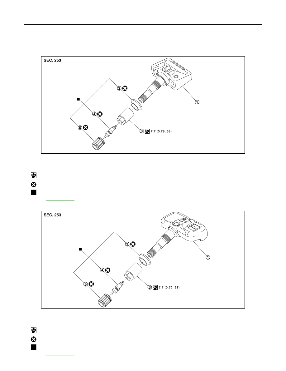
Exploded View
INFOID:0000000008462665
FOR SCHRADER TYPE
FOR PACIFIC TYPE
JSEIA0384GB
1.
Tire pressure sensor
2.
Grommet seal
3.
Valve nut
4.
Valve core
5.
Valve cap
: N·m (kg-m, in-lb)
: Always replace after every disassembly.
: Parts that are replaced as a set when the tire is replaced.
Refer to
for symbols not described above.
JSEIA0572GB
1.
Tire pressure sensor
2.
Grommet seal
3.
Valve nut
4.
Valve core
5.
Valve cap
: N·m (kg-m, in-lb)
: Always replace after every disassembly.
: Parts that are replaced as a set when the tire is replaced.
Refer to
for symbols not described above.
Revision: 2012 October
2013 Murano CrossCabriolet