Murano Cross Cabriolet Z51 (2013 year). Manual - part 95
ST-6
< PREPARATION >
PREPARATION
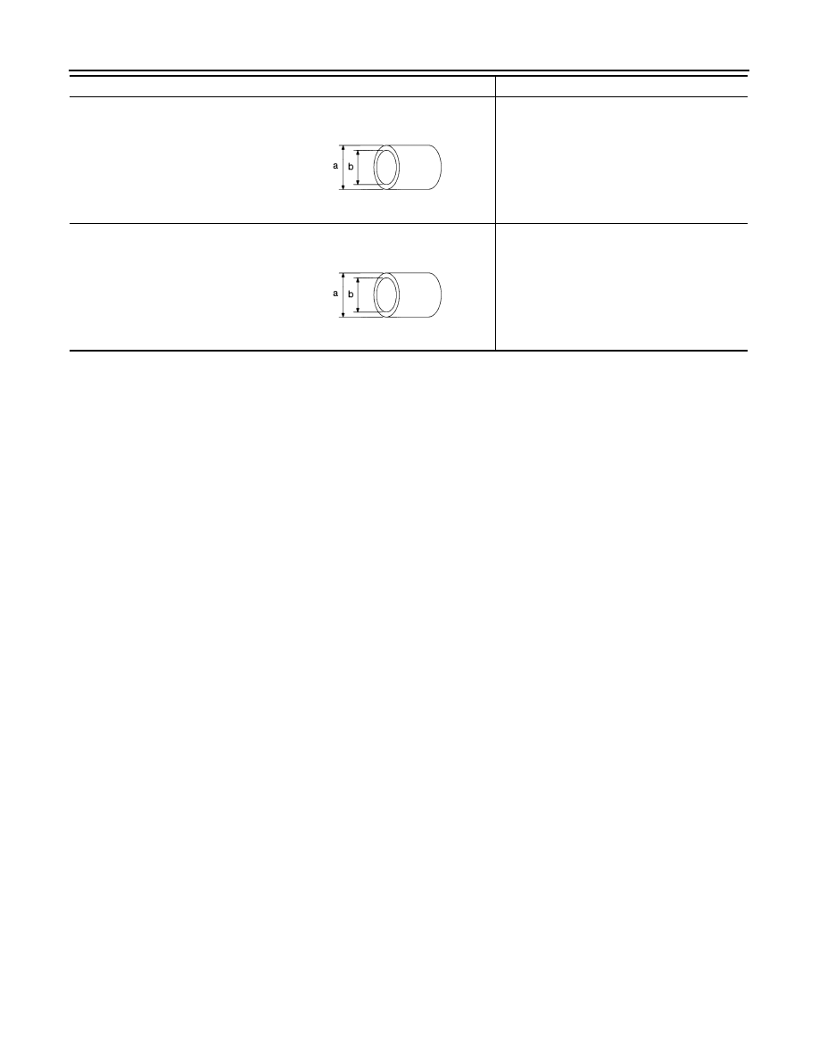
Drift
a: 15 mm (0.59 in) dia.
b: 10 mm (0.39 in) dia.
Installing rotor snap ring
Drift
a: 36 mm (1.42 in) dia.
b: 20 mm (0.79 in) dia.
Installing oil pump oil seal
Tool name
Description
S-NT474
S-NT474
Revision: 2012 October
2013 Murano CrossCabriolet