Murano Cross Cabriolet Z51 (2013 year). Manual - part 69


  Index      Manuals     Murano Cross Cabriolet Z51 (2013 year) - Service and Repair Manual


Search            copyright infringement  


Content      ..     67      68      69      70     ..


Murano Cross Cabriolet Z51 (2013 year). Manual - part 69


BCM, SOFT TOP CONTROL UNIT

PWC-13

< ECU DIAGNOSIS INFORMATION >

C

D

E

F

G

H

I

J

L

M

A

B

PWC

N

O

P

ECU DIAGNOSIS INFORMATION

BCM, SOFT TOP CONTROL UNIT

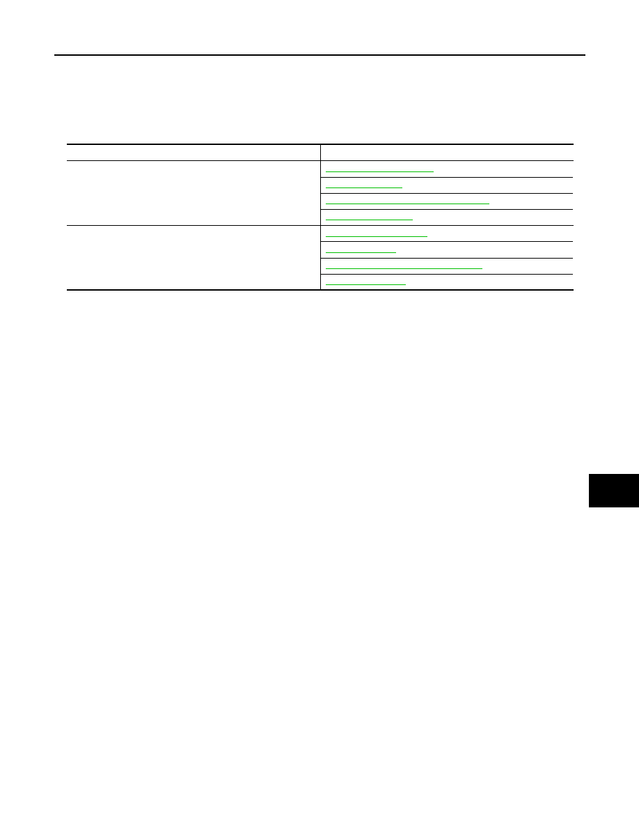
List of ECU Reference

INFOID:0000000008463213

ECU

Reference

BCM

BCS-32, "Reference Value"

BCS-54, "Fail-safe"

BCS-54, "DTC Inspection Priority Chart"

BCS-55, "DTC Index"

Soft top control unit

RF-45, "Reference Value"

RF-54, "Fail-safe"

RF-55, "DTC Inspection Priority Chart"

RF-57, "DTC Index"

Revision: 2012 October

2013 Murano CrossCabriolet

PWC-14

< ECU DIAGNOSIS INFORMATION >

POWER WINDOW MAIN SWITCH

POWER WINDOW MAIN SWITCH

Reference Value 

INFOID:0000000008463214

TERMINAL LAYOUT

PHYSICAL VALUES

LIIA2455E

Terminal No.

(Wire color)

Description

Condition

Voltage (V)

(Approx.)

+

-

Signal name 

Input/

Output

2

(W)

Ground

Encoder ground

0

4

(L)

Ground

Door key cylinder switch (driver 
side) LOCK signal

Input

Key position
(Neutral 

 Locked)

 0

5

(R)

Ground

Front door switch (driver side) 
signal

Input

OFF (when driver side door 
closed)

ON (when driver side door 
opened)

0

6

(R)

Ground

Door key cylinder switch (driver 
side) UNLOCK signal

Input

Key position
(Neutral 

 Unlocked)

 0

8

(L)

Ground

Front power window motor 
(driver side) UP signal

Output

When front LH switch in 
power window main switch 
is in UP operation.

12

9

(G)

Ground

Encoder pulse signal 2

Input

When front power window 
motor (driver side) operates.

10

(V)

Ground

Retained power signal

Input

Ignition switch ON

12

Within 45 seconds after igni-
tion switch is turned to OFF.

12

When driver side or passen-
ger side door is opened dur-
ing retained power 
operation.

0

JPMIA0011GB

JMKIA0070GB

Revision: 2012 October

2013 Murano CrossCabriolet

POWER WINDOW MAIN SWITCH

PWC-15

< ECU DIAGNOSIS INFORMATION >

C

D

E

F

G

H

I

J

L

M

A

B

PWC

N

O

P

Fail-safe

INFOID:0000000008463215

FAIL-SAFE CONTROL

Switches to fail-safe control when malfunction is detected in encoder signal that detects up/down speed and
direction of door glass. Switches to fail-safe control when error beyond regulation value is detected between
the fully closed position and the actual position of the glass.

It changes to condition before initialization and the following functions do not operate when switched to fail-
safe control.
• Auto-up operation
• Anti-pinch function
• Retained power function

Perform initial operation to recover when switched to fail-safe mode. However, it switches back to fail-safe
control when malfunction is found in power window switch or front power window motor.

11

(LG)

Ground

Front power window motor 
(driver side) DOWN signal

Output

When front LH switch in 
power window main switch 
is in DOWN operation.

 12

13

(Y)

Ground

Encoder pulse signal 1

Input

When front power window 
motor (driver side) operates.

14

(O)

Ground

Power window serial link

Input/

Output

Ignition switch ON or power 
window timer operating.

15

(R)

Ground

Encoder power supply

Output

When ignition switch ON or 
power window timer oper-
ates.

12

17

(B)

Ground

Ground

0

19

(LG)

Ground

Battery power supply

Input

Ignition switch OFF

12

Terminal No.

(Wire color)

Description

Condition

Voltage (V)

(Approx.)

+

-

Signal name 

Input/

Output

JMKIA0070GB

JPMIA0013GB

Error

Error condition

Pulse sensor malfunction

When only one side of pulse signal is being detected for more than the specified value.

Both pulse sensors mal-
function

When both pulse signals have not been detected for more than the specified value during glass open/
close operation.

Pulse direction malfunction

When the pulse signal that is detected during glass open/close operation detects the opposite condition 
of power window motor operating direction.

Glass recognition position 
malfunction 1

When it detects the error between glass fully closed position in power window switch memory and actual 
fully closed position during glass open/close operation is more than the specified value.

Glass recognition position 
malfunction 2

When it detects pulse count more than the value of glass full stroke during glass open/close operation.

Revision: 2012 October

2013 Murano CrossCabriolet

PWC-16

< ECU DIAGNOSIS INFORMATION >

FRONT POWER WINDOW SWITCH (PASSENGER SIDE)

FRONT POWER WINDOW SWITCH (PASSENGER SIDE)

Reference Value 

INFOID:0000000008463216

TERMINAL LAYOUT

PHYSICAL VALUES

LIIA2454E

Terminal No.

(Wire color)

Description

Condition

Voltage [V]

(Approx.)

+

-

Signal name

Input/

Output

3

(W)

Ground

Encoder ground

0

4

(R)

Ground

Encoder power supply

Output

When ignition switch ON or 
power window timer operates.

 12

8

(L)

Ground

Front power window mo-
tor (passenger side) UP 
signal

Output

When front RH switch in power 
window main switch is in UP op-
eration.

 12

9

(LG)

Ground

Front power window mo-
tor (passenger side) 
DOWN signal

Output

When front RH switch in power 
window main switch is in DOWN 
operation.

12

10

(P)

Ground

Battery power supply

Input

Ignition switch OFF

12

11

(B)

Ground

Ground

0

12

(Y)

Ground

Encoder pulse signal 1

Input

When front power window motor 
(passenger side) operates.

14

(R)

Ground

Front door switch (pas-
senger side) signal

Input

OFF (when passenger side door 
closed)

ON (when passenger side door 
opened)

0

JMKIA0070GB

JPMIA0011GB

Revision: 2012 October

2013 Murano CrossCabriolet

FRONT POWER WINDOW SWITCH (PASSENGER SIDE)

PWC-17

< ECU DIAGNOSIS INFORMATION >

C

D

E

F

G

H

I

J

L

M

A

B

PWC

N

O

P

Fail-safe

INFOID:0000000008463217

FAIL-SAFE CONTROL

Switches to fail-safe control when malfunction is detected in encoder signal that detects up/down speed and
direction of door glass. Switches to fail-safe control when error beyond regulation value is detected between
the fully closed position and the actual position of the glass.

It changes to condition before initialization and the following functions do not operate when switched to fail-
safe control.
• Auto-up operation
• Anti-pinch function
• Retained power function

Perform initial operation to recover when switched to fail-safe mode. However, it switches back to fail-safe
control when malfunction is found in power window switch or front power window motor.

15

(G)

Ground

Encoder pulse signal 2

Input

When front power window motor 
(passenger side) operates.

16

(O)

Ground

Power window serial link

Input/

Output

Ignition switch ON or power win-
dow timer operating.

Terminal No.

(Wire color)

Description

Condition

Voltage [V]

(Approx.)

+

-

Signal name

Input/

Output

JMKIA0070GB

JPMIA0013GB

Error

Error condition

Pulse sensor malfunction

When only one side of pulse signal is being detected for more than the specified value.

Both pulse sensors mal-
function

When both pulse signals have not been detected for more than the specified value during glass open/
close operation.

Pulse direction malfunction

When the pulse signal that is detected during glass open/close operation detects the opposite condition 
of power window motor operating direction.

Glass recognition position 
malfunction 1

When it detects the error between glass fully closed position in power window switch memory and actual 
fully closed position during glass open/close operation is more than the specified value.

Glass recognition position 
malfunction 2

When it detects pulse count more than the value of glass full stroke during glass open/close operation.

Revision: 2012 October

2013 Murano CrossCabriolet

PWC-18

< ECU DIAGNOSIS INFORMATION >

REAR POWER WINDOW SWITCH LH

REAR POWER WINDOW SWITCH LH

Reference Value 

INFOID:0000000008463218

TERMINAL LAYOUT

PHYSICAL VALUES

LIIA2454E

Terminal No.

(wire color)

Description

Condition

Voltage [V]

(Approx.)

+

-

Signal name

Input/

Output

3

(W)

Ground

Encoder ground

0

4

(R)

Ground

Encoder power supply

Output

When ignition switch ON or pow-
er window timer operates.

 12

8

(L)

Ground

Rear power window mo-
tor LH UP signal

Output

When rear LH switch in power 
window main switch is in UP op-
eration.

 12

9

(LG)

Ground

Rear power window mo-
tor LH DOWN signal

Output

When rear LH switch in power 
window main switch is in DOWN 
operation.

 12

10

(P)

Ground

Battery power supply

Input

Ignition switch OFF

 Battery voltage

11

(B)

Ground

Ground

0

12

(Y)

Ground

Encoder pulse signal 1

Input

When rear power window motor 
LH operates.

JMKIA0070GB

Revision: 2012 October

2013 Murano CrossCabriolet

REAR POWER WINDOW SWITCH LH

PWC-19

< ECU DIAGNOSIS INFORMATION >

C

D

E

F

G

H

I

J

L

M

A

B

PWC

N

O

P

Fail-safe

INFOID:0000000008463219

FAIL-SAFE CONTROL

Switches to fail-safe control when malfunction is detected in encoder signal that detects up/down speed and
direction of door glass. Switches to fail-safe control when error beyond regulation value is detected between
the fully closed position and the actual position of the glass.

It changes to condition before initialization and the following functions do not operate when switched to fail-
safe control.
• Auto-up operation
• Anti-pinch function
• Retained power function

Perform initial operation to recover when switched to fail-safe mode. However, it switches back to fail-safe
control when malfunction is found in power window switch or front power window motor.

15

(O)

Ground

Encoder pulse signal 2

Input

When rear power window motor 
LH operates.

16

(G)

Ground

Power window serial link

Input/

Output

When ignition switch ON or pow-
er window timer operates.

Terminal No.

(wire color)

Description

Condition

Voltage [V]

(Approx.)

+

-

Signal name

Input/

Output

JMKIA0070GB

JPMIA0013GB

Error

Error condition

Pulse sensor malfunction

When only one side of pulse signal is being detected for more than the specified value.

Both pulse sensors mal-
function

When both pulse signals have not been detected for more than the specified value during glass open/
close operation.

Pulse direction malfunction

When the pulse signal that is detected during glass open/close operation detects the opposite condition 
of power window motor operating direction.

Glass recognition position 
malfunction 1

When it detects the error between glass fully closed position in power window switch memory and actual 
fully closed position during glass open/close operation is more than the specified value.

Glass recognition position 
malfunction 2

When it detects pulse count more than the value of glass full stroke during glass open/close operation.

Revision: 2012 October

2013 Murano CrossCabriolet

PWC-20

< ECU DIAGNOSIS INFORMATION >

REAR POWER WINDOW SWITCH RH

REAR POWER WINDOW SWITCH RH

Reference Value 

INFOID:0000000008463220

TERMINAL LAYOUT

PHYSICAL VALUES

LIIA2454E

Terminal No.

(wire color)

Description

Condition

Voltage [V]

(Approx.)

+

-

Signal name

Input/

Output

3

(W)

Ground

Encoder ground

0

4

(R)

Ground

Encoder power supply

Output

When ignition switch ON or pow-
er window timer operates.

 12

8

(L)

Ground

Rear power window mo-
tor RH UP signal

Output

When rear RH switch in power 
window main switch is in UP op-
eration.

 12

9

(LG)

Ground

Rear power window mo-
tor RH DOWN signal

Output

When rear RH switch in power 
window main switch is in DOWN 
operation.

 12

10

(GR)

Ground

Battery power supply

Input

Ignition switch OFF

 Battery voltage

11

(B)

Ground

Ground

0

12

(Y)

Ground

Encoder pulse signal 1

Input

When rear power window motor 
RH operates.

JMKIA0070GB

Revision: 2012 October

2013 Murano CrossCabriolet

REAR POWER WINDOW SWITCH RH

PWC-21

< ECU DIAGNOSIS INFORMATION >

C

D

E

F

G

H

I

J

L

M

A

B

PWC

N

O

P

Fail-safe

INFOID:0000000008463221

FAIL-SAFE CONTROL

Switches to fail-safe control when malfunction is detected in encoder signal that detects up/down speed and
direction of door glass. Switches to fail-safe control when error beyond regulation value is detected between
the fully closed position and the actual position of the glass.

It changes to condition before initialization and the following functions do not operate when switched to fail-
safe control.
• Auto-up operation
• Anti-pinch function
• Retained power function

Perform initial operation to recover when switched to fail-safe mode. However, it switches back to fail-safe
control when malfunction is found in power window switch or front power window motor.

15

(G)

Ground

Encoder pulse signal 2

Input

When rear power window motor 
RH operates.

16

(G)

Ground

Power window serial link

Input/

Output

When ignition switch ON or pow-
er window timer operates.

Terminal No.

(wire color)

Description

Condition

Voltage [V]

(Approx.)

+

-

Signal name

Input/

Output

JMKIA0070GB

JPMIA0013GB

Error

Error condition

Pulse sensor malfunction

When only one side of pulse signal is being detected for more than the specified value.

Both pulse sensors mal-
function

When both pulse signals have not been detected for more than the specified value during glass open/
close operation.

Pulse direction malfunction

When the pulse signal that is detected during glass open/close operation detects the opposite condition 
of power window motor operating direction.

Glass recognition position 
malfunction 1

When it detects the error between glass fully closed position in power window switch memory and actual 
fully closed position during glass open/close operation is more than the specified value.

Glass recognition position 
malfunction 2

When it detects pulse count more than the value of glass full stroke during glass open/close operation.

Revision: 2012 October

2013 Murano CrossCabriolet

PWC-22

< WIRING DIAGRAM >

POWER WINDOW SYSTEM

WIRING DIAGRAM

POWER WINDOW SYSTEM

Wiring Diagram

INFOID:0000000008463222

For connector terminal arrangements, harness layouts, and alphabets in a 

 (option abbreviation; if not

described in wiring diagram), refer to 

GI-12, "Connector Information"

.

JRKWC1073GB

Revision: 2012 October

2013 Murano CrossCabriolet

DIAGNOSIS AND REPAIR WORK FLOW

PWC-23

< BASIC INSPECTION >

C

D

E

F

G

H

I

J

L

M

A

B

PWC

N

O

P

BASIC INSPECTION

DIAGNOSIS AND REPAIR WORK FLOW

Work Flow

INFOID:0000000008463223

1.

OBTAIN INFORMATION ABOUT SYMPTOM

Interview the customer to obtain the malfunction information (conditions and environment when the malfunc-
tion occurred) as much as possible when the customer brings the vehicle in.

>> GO TO 2.

2.

REPRODUCE THE MALFUNCTION INFORMATION

Check the malfunction on the vehicle that the customer describes.
Inspect the relation of the symptoms and the condition when the symptoms occur.

>> GO TO 3.

3.

IDENTIFY THE MALFUNCTIONING SYSTEM WITH “SYMPTOM DIAGNOSIS”

Use “Symptom diagnosis” from the symptom inspection result in step 2 and then identify where to start per-
forming the diagnosis based on possible causes and symptoms.

>> GO TO 4.

4.

IDENTIFY THE MALFUNCTIONING PARTS WITH “DTC/CIRCUIT DIAGNOSIS”

Perform the diagnosis with “DTC/CIRCUIT DIAGNOSIS” of the applicable system.

>> GO TO 5.

5.

REPAIR OR REPLACE THE MALFUNCTIONING PARTS

Repair or replace the specified malfunctioning parts.

>> GO TO 6.

6.

FINAL CHECK

Check that malfunctions are not reproduced when obtaining the malfunction information from the customer,
referring to the symptom inspection result in step 2.
Are the malfunctions corrected?

YES

>> INSPECTION END

NO

>> GO TO 3.

Revision: 2012 October

2013 Murano CrossCabriolet

PWC-24

< BASIC INSPECTION >

ADDITIONAL SERVICE WHEN REMOVING BATTERY NEGATIVE TERMINAL

ADDITIONAL SERVICE WHEN REMOVING BATTERY NEGATIVE TERMI-
NAL

Description

INFOID:0000000008463224

When the battery negative terminal is disconnected, the initialization is necessary for normal operation of
power window system.

CAUTION:

The following specified operations can not be performed under the non-initialized condition.
• Auto-up operation
• Anti-pinch function
• Automatic window adjusting function

Work Procedure

INFOID:0000000008463225

1.

SYSTEM INITIALIZATION

Perform system initialization. Refer to 

PWC-26, "Work Procedure"

.

>> GO TO 2.

2.

CHECK ANTI-PINCH FUNCTION

Check anti-pinch function. Refer to 

PWC-27, "Work Procedure"

.

>> END

Revision: 2012 October

2013 Murano CrossCabriolet

ADDITIONAL SERVICE WHEN REPLACING POWER WINDOW SWITCH

PWC-25

< BASIC INSPECTION >

C

D

E

F

G

H

I

J

L

M

A

B

PWC

N

O

P

ADDITIONAL SERVICE WHEN REPLACING POWER WINDOW SWITCH

Description

INFOID:0000000008463226

When the power window main switch or front power window switch (passenger side) replaced, the initialization
in necessary for normal operation of power window system.

CAUTION:

The following specified operations can not be performed under the non-initialized condition.
• Auto-up operation
• Anti-pinch function
• Automatic window adjusting function

Work Procedure

INFOID:0000000008463227

1.

SYSTEM INITIALIZATION

Perform system initialization. Refer to 

PWC-26, "Work Procedure"

.

>> GO TO 2.

2.

CHECK ANTI-PINCH FUNCTION

Check anti-pinch function. Refer to 

PWC-27, "Work Procedure"

.

>> END

Revision: 2012 October

2013 Murano CrossCabriolet

PWC-26

< BASIC INSPECTION >

SYSTEM INITIALIZATION

SYSTEM INITIALIZATION

Description

INFOID:0000000008463228

If any of the following operations are performed, the initialization is necessary for normal operation of power
window system.
• Disconnection and connection of battery cable from negative terminal.
• When power window main switch or front power window switch (passenger side) replaced.
• Electric power supply to power window main switch or front power window switch (passenger side) or power

window motor (driver side/passenger side) is interrupted by blown fuse or disconnection and connection of
the negative terminal of battery, etc.

• Disconnection and connection of power window main switch or front power window switch (passenger side)

harness connector.

• Removal of power window motor (driver side/passenger side) from module assembly.
• Operation of module assembly as an independent unit.
• Removal of regulator assembly from module assembly.
• Removal and installation of glass.
• Removal and installation of weather-strip.
• Removal and installation of door glass run.

CAUTION:

The following specified operations can not be performed under the non-initialized condition.
• Auto-up operation
• Anti-pinch function
• Automatic window adjusting function

Work Procedure

INFOID:0000000008463229

1.

STEP 1

1.

Turn ignition switch ON.

2.

Close roof.

3.

Operate power window switch to fully open the window. (This operation is unnecessary if the window is
already fully open)

4.

Continue pulling the power window switch UP (AUTO-UP operation). Even after glass stops at fully closed
position, keep pulling the switch for 2 seconds or more.

5.

Check that AUTO-UP function operates normally.

>> GO TO 2.

2.

STEP 2

Check anti-pinch function. Refer to 

PWC-27, "Work Procedure"

.

>> END

Revision: 2012 October

2013 Murano CrossCabriolet

CHECK ANTI-PINCH FUNCTION

PWC-27

< BASIC INSPECTION >

C

D

E

F

G

H

I

J

L

M

A

B

PWC

N

O

P

CHECK ANTI-PINCH FUNCTION

Description

INFOID:0000000008463230

If any of the following operations are performed, the initialization is necessary for normal operation of anti-
pinch function.
• Disconnection and connection of battery cable from negative terminal.
• When power window main switch or front power window switch (passenger side) replaced.
• Electric power supply to power window main switch or front power window switch (passenger side) or power

window motor (driver side/passenger side) is interrupted by blown fuse or disconnection and connection of
the negative terminal of battery, etc.

• Disconnection and connection of power window main switch or front power window switch (passenger side)

harness connector.

• Removal of power window motor (driver side/passenger side) from regulator assembly.
• Operation of regulator assembly as an independent unit.
• Removal and installation of glass.
• Removal and installation of door glass run.

Work Procedure

INFOID:0000000008463231

1.

CHECK ANTI-PINCH FUNCTION

1.

Fully open the door window.

2.

Place a piece of wood near fully closed position.

3.

Close door glass completely with AUTO-UP.

4.

Check the following conditions.

-

Check that glass lowers for approximately 150 mm (5.9 in) without pinching piece of wood and stops.

-

Check that glass does not rise not when operating the power window main switch or front power window
switch (passenger side) while lowering.

CAUTION:

Perform initial setting when AUTO-UP operation or anti-pinch function does not operate nor-
mally.

Check that AUTO-UP operates before inspection when system initialization is performed.

Do not check with hands and other body parts because they may be pinched. Do not get
pinched.

>> END

Revision: 2012 October

2013 Murano CrossCabriolet

PWC-28

< DTC/CIRCUIT DIAGNOSIS >

POWER SUPPLY AND GROUND CIRCUIT

DTC/CIRCUIT DIAGNOSIS

POWER SUPPLY AND GROUND CIRCUIT

POWER WINDOW MAIN SWITCH

POWER WINDOW MAIN SWITCH : Diagnosis Procedure

INFOID:0000000008463232

1.

CHECK POWER SUPPLY 

1.

Turn ignition switch OFF.

2.

Disconnect power window main switch connector.

3.

Check voltage between power window main switch harness connector and ground.

Is the inspection result normal?

YES

>>  GO TO 3.

NO

>>  GO TO 2.

2.

CHECK POWER SUPPLY CIRCUIT 

1.

Turn ignition switch OFF.

2.

Disconnect BCM connector.

3.

Check continuity between BCM harness connector and power window main switch harness connector.

4.

Check continuity between BCM harness connector and ground.

Is the inspection result normal?

YES

>>  Replace BCM. Refer to 

BCS-77, "Removal and Installation"

.

NO

>>  Repair or replace harness.

3.

CHECK GROUND CIRCUIT

Check continuity between power window main switch harness connector and ground.

Is the inspection result normal?

YES

>>  INSPECTION END

NO

>>  Repair or replace harness.

FRONT POWER WINDOW SWITCH (PASSENGER SIDE)

(+)

(–)

Condition

Voltage (V)

(Approx.)

Power window main switch

Connector

Terminal 

D5

10

Ground

Ignition switch

ON

12

D6

19

OFF

BCM

Power window main switch

Continuity

Connector

Terminal

Connector

Terminal

M118

2

D6

19

Existed

3

D5

10

BCM

Ground

Continuity

Connector

Terminal

M118

2

Not existed

3

Power window main switch 

Ground

Continuity 

Connector

Terminal

D6

17

Existed

Revision: 2012 October

2013 Murano CrossCabriolet


Content      ..     67      68      69      70     ..