Murano Cross Cabriolet Z51 (2013 year). Manual - part 68


  Index      Manuals     Murano Cross Cabriolet Z51 (2013 year) - Service and Repair Manual


Search            copyright infringement  


Content      ..     66      67      68      69     ..


Murano Cross Cabriolet Z51 (2013 year). Manual - part 68


PCS-68

< DTC/CIRCUIT DIAGNOSIS >

[POWER DISTRIBUTION SYSTEM]

PUSH-BUTTON IGNITION SWITCH POSITION INDICATOR

2.

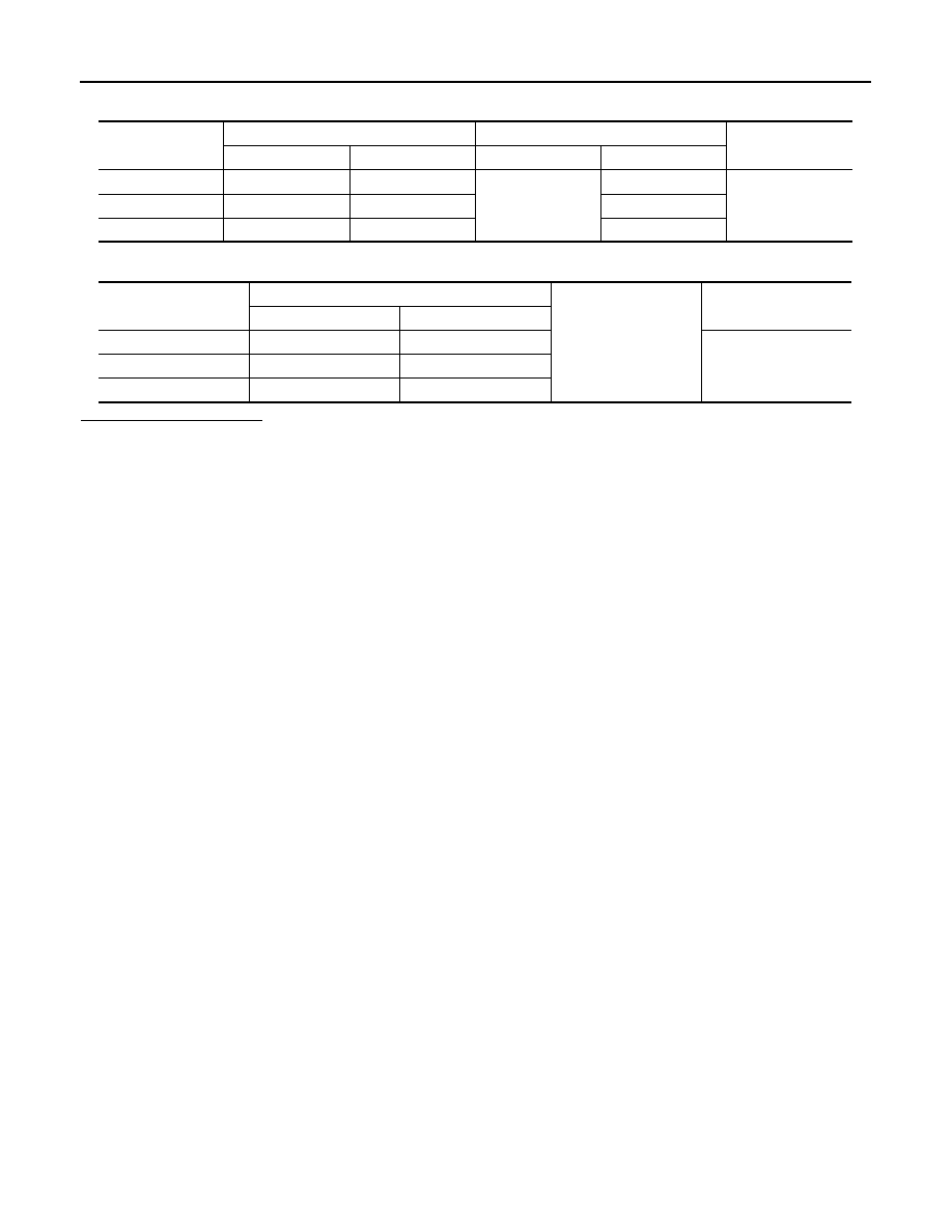
Check continuity between BCM harness connector and push-button ignition switch harness connector.

3.

Check continuity between BCM harness connector and ground.

Is the inspection normal?

YES

>> Replace push-button ignition switch.

NO

>> Repair or replace harness.

Indicator

BCM

Push-button ignition switch

Continuity

Connector

Terminal

Connector

Terminal

LOCK

M123

134

M101

5

Existed

ACC

M119

15

6

ON

M122

93

7

Indicator

BCM

Ground

Continuity

Connector

Terminal

LOCK

M123

134

Not existed

ACC

M119

15

ON

M122

93

Revision: 2012 October

2013 Murano CrossCabriolet

PCS

PUSH-BUTTON IGNITION SWITCH DOES NOT OPERATE

PCS-69

< SYMPTOM DIAGNOSIS >

[POWER DISTRIBUTION SYSTEM]

C

D

E

F

G

H

I

J

K

L

B

A

O

P

N

SYMPTOM DIAGNOSIS

PUSH-BUTTON IGNITION SWITCH DOES NOT OPERATE

Description

INFOID:0000000008463362

Check that vehicle is under the condition shown in “Conditions of vehicle” before starting diagnosis, and check
each symptom.
NOTE:
The engine start function, door lock function, power distribution system, and NATS-IVIS/NVIS in the Intelligent
Key system are closely related to each other regarding control. The vehicle security function can operate only
when the door lock and power distribution system are operating normally.

Conditions of Vehicle (Operating Conditions)

• “ENGINE START BY I-KEY” in “WORK SUPPORT” is ON when setting on CONSULT.
• Intelligent Key is not inserted in key slot.
• One or more of Intelligent Keys with registered Intelligent Key ID is in the vehicle.

Diagnosis Procedure

INFOID:0000000008463363

1.

PERFORM WORK SUPPORT

Perform “INSIDE ANT DIAGNOSIS” on Work Support of “INTELLIGENT KEY”.
Refer to 

DLK-35, "INTELLIGENT KEY : CONSULT Function (BCM - INTELLIGENT KEY)"

.

>> GO TO 2.

2.

PERFORM SELF-DIAGNOSTIC RESULT

Perform Self-Diagnostic Result of “BCM”.
Is DTC detected?

YES

>> Refer to 

BCS-55, "DTC Index"

.

NO

>> GO TO 3.

3.

CHECK PUSH-BUTTON IGNITION SWITCH

Check push-button ignition switch.
Refer to 

PCS-65, "Component Function Check"

.

Is the operation normal?

YES

>> GO TO 4.

NO

>> Repair or replace malfunctioning parts.

4.

CONFIRM THE OPERATION

Confirm the operation again.

Is the inspection normal?

YES

>> Check intermittent incident. Refer to 

GI-40, "Intermittent Incident"

.

NO

>> GO TO 1.

Revision: 2012 October

2013 Murano CrossCabriolet

PCS-70

< SYMPTOM DIAGNOSIS >

[POWER DISTRIBUTION SYSTEM]

PUSH-BUTTON IGNITION SWITCH POSITION INDICATOR DOES NOT ILLUMI-

NATE

PUSH-BUTTON IGNITION SWITCH POSITION INDICATOR DOES NOT IL-
LUMINATE

Description

INFOID:0000000008463364

• Before performing the diagnosis in the following table, check “Work Flow”. Refer to 

PCS-47, "Work Flow"

.

• Check that vehicle is under the condition shown in “Conditions of vehicle” before starting diagnosis, and

check each symptom.

Conditions of Vehicle (Operating Conditions)

• “ENGINE START BY I-KEY” in “WORK SUPPORT” is ON when setting on CONSULT.
• One or more of Intelligent Keys with registered Intelligent Key ID is in the vehicle.

Diagnosis Procedure

INFOID:0000000008463365

1.

CHECK PUSH-BUTTON IGNITION SWITCH INDICATOR

Check push-button ignition switch indicator.
Refer to 

PCS-67, "Component Function Check"

.

Is the inspection result normal?

YES

>> GO TO 2.

NO

>> Repair or replace the malfunctioning parts.

2.

CONFIRM THE OPERATION

Confirm the operation again.

Is the result normal?

YES

>> Check intermittent incident. Refer to 

GI-40, "Intermittent Incident"

.

NO

>> GO TO 1.

Revision: 2012 October

2013 Murano CrossCabriolet

PCS

PUSH-BUTTON IGNITION SWITCH

PCS-71

< REMOVAL AND INSTALLATION >

[POWER DISTRIBUTION SYSTEM]

C

D

E

F

G

H

I

J

K

L

B

A

O

P

N

REMOVAL AND INSTALLATION

PUSH-BUTTON IGNITION SWITCH

Exploded View

INFOID:0000000008463366

Removal and Installation

INFOID:0000000008463367

REMOVAL

1.

Remove the instrument stay cover LH. Refer to 

IP-13, "Removal and Installation"

.

2.

Remove the push-button ignition switch (1) from instrument stay
cover LH, after removing pawl (A). Press push-button ignition
switch (1) back to disengage from instrument stay cover LH (2).

INSTALLATION

Install in the reverse order of removal.

1.

Push-button ignition switch

JMKIA1812ZZ

JMKIA1813ZZ

Revision: 2012 October

2013 Murano CrossCabriolet

PWC-1

BODY EXTERIOR, DOORS, ROOF & VEHICLE SECURITY

C

D

E

F

G

H

I

J

L

M

SECTION 

PWC

A

B

PWC

N

O

P

CONTENTS

POWER WINDOW CONTROL SYSTEM

PRECAUTION ...............................................

4

PRECAUTIONS ...................................................

4

Precaution for Supplemental Restraint System 
(SRS) "AIR BAG" and "SEAT BELT PRE-TEN-
SIONER" .................................................................
..

4

Service Procedure Precautions for Models with a 
Pop-up Roll Bar .......................................................
..

4

Precaution for Battery Service  ..................................

4

SYSTEM DESCRIPTION  ..............................

5

COMPONENT PARTS  ........................................

5

Component Parts Location ......................................

5

Component Description .............................................

6

SYSTEM ..............................................................

7

System Diagram .......................................................

7

System Description  ...................................................

7

Fail-safe ....................................................................

9

DIAGNOSIS SYSTEM (BCM)  ............................

10

COMMON ITEM  .........................................................

10

COMMON ITEM : CONSULT Function (BCM - 
COMMON ITEM) .....................................................

10

RETAINED PWR  .......................................................

11

RETAINED PWR : CONSULT Function (BCM - 
RETAINED PWR)  ...................................................

11

ECU DIAGNOSIS INFORMATION ..............

13

BCM, SOFT TOP CONTROL UNIT ....................

13

List of ECU Reference  ............................................

13

POWER WINDOW MAIN SWITCH  ....................

14

Reference Value  .....................................................

14

Fail-safe ..................................................................

15

FRONT POWER WINDOW SWITCH (PAS-
SENGER SIDE)  ..................................................

16

Reference Value  .....................................................

16

Fail-safe ...................................................................

17

REAR POWER WINDOW SWITCH LH  ............

18

Reference Value ......................................................

18

Fail-safe ...................................................................

19

REAR POWER WINDOW SWITCH RH  ............

20

Reference Value ......................................................

20

Fail-safe ...................................................................

21

WIRING DIAGRAM  ......................................

22

POWER WINDOW SYSTEM .............................

22

Wiring Diagram ........................................................

22

BASIC INSPECTION  ...................................

23

DIAGNOSIS AND REPAIR WORK FLOW  .......

23

Work Flow ................................................................

23

ADDITIONAL SERVICE WHEN REMOVING 
BATTERY NEGATIVE TERMINAL  ...................

24

Description ...............................................................

24

Work Procedure .......................................................

24

ADDITIONAL SERVICE WHEN REPLACING 
POWER WINDOW SWITCH  .............................

25

Description ...............................................................

25

Work Procedure .......................................................

25

SYSTEM INITIALIZATION ................................

26

Description ...............................................................

26

Work Procedure .......................................................

26

CHECK ANTI-PINCH FUNCTION .....................

27

Description ...............................................................

27

Work Procedure .......................................................

27

DTC/CIRCUIT DIAGNOSIS  .........................

28

POWER SUPPLY AND GROUND CIRCUIT  ....

28

POWER WINDOW MAIN SWITCH ............................

28

Revision: 2012 October

2013 Murano CrossCabriolet

PWC-2

POWER WINDOW MAIN SWITCH : Diagnosis 
Procedure ..............................................................
.

28

FRONT POWER WINDOW SWITCH (PASSEN-
GER SIDE)  ...............................................................
.

28

FRONT POWER WINDOW SWITCH (PASSEN-
GER SIDE) : Diagnosis Procedure  ........................
.

29

REAR POWER WINDOW SWITCH  ..........................

29

REAR POWER WINDOW SWITCH : Diagnosis 
Procedure ..............................................................
.

29

POWER WINDOW MOTOR ...............................

31

DRIVER SIDE ............................................................

31

DRIVER SIDE : Component Function Check  .........

31

DRIVER SIDE : Diagnosis Procedure  ....................

31

PASSENGER SIDE ...................................................

31

PASSENGER SIDE : Component Function Check 

...

32

PASSENGER SIDE : Diagnosis Procedure  ...........

32

REAR LH ...................................................................

32

REAR LH : Component Function Check  ................

33

REAR LH : Diagnosis Procedure ............................

33

REAR RH  ..................................................................

33

REAR RH : Component Function Check  ................

33

REAR RH : Diagnosis Procedure  ...........................

34

ENCODER CIRCUIT ..........................................

35

DRIVER SIDE ............................................................

35

DRIVER SIDE : Component Function Check  .........

35

DRIVER SIDE : Diagnosis Procedure  ....................

35

PASSENGER SIDE ...................................................

37

PASSENGER SIDE : Component Function Check 

...

37

PASSENGER SIDE : Diagnosis Procedure  ...........

37

REAR LH ...................................................................

39

REAR LH : Component Function Check  ................

39

REAR LH : Diagnosis Procedure ............................

39

REAR RH  ..................................................................

41

REAR RH : Component Function Check  ................

41

REAR RH : Diagnosis Procedure  ...........................

41

DOOR KEY CYLINDER SWITCH ......................

44

Component Function Check  ...................................

44

Diagnosis Procedure  ..............................................

44

Component Inspection ............................................

45

POWER WINDOW SERIAL LINK  .....................

46

POWER WINDOW MAIN SWITCH  ...........................

46

POWER WINDOW MAIN SWITCH : Diagnosis 
Procedure ..............................................................
.

46

FRONT POWER WINDOW SWITCH (PASSEN-
GER SIDE)  ...............................................................
.

47

FRONT POWER WINDOW SWITCH (PASSEN-
GER SIDE) : Diagnosis Procedure  .........................

47

REAR POWER WINDOW SWITCH LH .....................

47

REAR POWER WINDOW SWITCH LH : Diagno-
sis Procedure  ..........................................................

47

REAR POWER WINDOW SWITCH RH  ....................

48

REAR POWER WINDOW SWITCH RH : Diagno-
sis Procedure  ..........................................................

48

DOOR SWITCH  .................................................

50

DRIVER SIDE  ............................................................

50

DRIVER SIDE : Component Function Check  .........

50

DRIVER SIDE : Diagnosis Procedure .....................

50

PASSENGER SIDE  ...................................................

50

PASSENGER SIDE : Component Function Check 

...

50

PASSENGER SIDE : Diagnosis Procedure ............

50

SYMPTOM DIAGNOSIS  ............................

52

NONE OF THE POWER WINDOWS CAN BE 
OPERATED USING ANY SWITCH  ...................

52

Diagnosis Procedure ...............................................

52

DRIVER SIDE POWER WINDOW DOES NOT 
OPERATE ..........................................................

53

Diagnosis Procedure ...............................................

53

FRONT PASSENGER SIDE POWER WIN-
DOW DOES NOT OPERATE  ............................

54

WHEN BOTH POWER WINDOW MAIN SWITCH 
AND FRONT POWER WINDOW SWITCH ARE 
OPERATED ...............................................................

54

WHEN BOTH POWER WINDOW MAIN SWITCH 
AND FRONT POWER WINDOW SWITCH ARE 
OPERATED : Diagnosis Procedure ........................

54

WHEN FRONT POWER WINDOW SWITCH (PAS-
SENGER SIDE) IS OPERATED  ................................

54

WHEN FRONT POWER WINDOW SWITCH 
(PASSENGER SIDE) IS OPERATED : Diagnosis 
Procedure ...............................................................

54

WHEN POWER WINDOW MAIN SWITCH IS OP-
ERATED ....................................................................

54

WHEN POWER WINDOW MAIN SWITCH IS OP-
ERATED : Diagnosis Procedure  .............................

54

REAR LH SIDE POWER WINDOW DOES 
NOT OPERATE  .................................................

55

WHEN BOTH POWER WINDOW MAIN SWITCH 
AND REAR POWER WINDOW SWITCH LH ARE 
OPERATED ...............................................................

55

WHEN BOTH POWER WINDOW MAIN SWITCH 
AND REAR POWER WINDOW SWITCH LH ARE 
OPERATED : Diagnosis Procedure ........................

55

Revision: 2012 October

2013 Murano CrossCabriolet

PWC-3

C

D

E

F

G

H

I

J

L

M

A

B

PWC

N

O

P

WHEN REAR POWER WINDOW SWITCH LH IS 
OPERATED ...............................................................

55

WHEN REAR POWER WINDOW SWITCH LH IS 
OPERATED : Diagnosis Procedure  ........................

55

WHEN POWER WINDOW MAIN SWITCH IS OP-
ERATED ....................................................................

55

WHEN POWER WINDOW MAIN SWITCH IS OP-
ERATED : Diagnosis Procedure  .............................

55

REAR RH SIDE POWER WINDOW DOES 
NOT OPERATE  ..................................................

56

WHEN BOTH POWER WINDOW MAIN SWITCH 
AND REAR POWER WINDOW SWITCH RH ARE 
OPERATED ...............................................................

56

WHEN BOTH POWER WINDOW MAIN SWITCH 
AND REAR POWER WINDOW SWITCH RH ARE 
OPERATED : Diagnosis Procedure  ........................

56

WHEN REAR POWER WINDOW SWITCH RH IS 
OPERATED ...............................................................

56

WHEN REAR POWER WINDOW SWITCH RH IS 
OPERATED : Diagnosis Procedure  ........................

56

WHEN POWER WINDOW MAIN SWITCH IS OP-
ERATED ....................................................................

56

WHEN POWER WINDOW MAIN SWITCH IS OP-
ERATED : Diagnosis Procedure  .............................

56

AUTO OPERATION DOES NOT OPERATE 
BUT MANUAL OPERATES NORMALLY  ..........

57

DRIVER SIDE  ............................................................

57

DRIVER SIDE : Diagnosis Procedure  .....................

57

PASSENGER SIDE  ...................................................

57

PASSENGER SIDE : Diagnosis Procedure  ............

57

REAR LH  ...................................................................

57

REAR LH : Diagnosis Procedure  ............................

58

REAR RH  ...................................................................

58

REAR RH : Diagnosis Procedure ............................

58

ANTI-PINCH FUNCTION DOES NOT OPER-
ATE NORMALLY  ...............................................

59

Diagnosis Procedure ...............................................

59

AUTOMATIC WINDOW ADJUSTING FUNC-
TION DOES NOT OPERATE  ............................

60

DRIVER SIDE .............................................................

60

DRIVER SIDE : Diagnosis Procedure  .....................

60

PASSENGER SIDE ....................................................

60

PASSENGER SIDE : Diagnosis Procedure  ............

60

POWER WINDOW RETAINED POWER OP-
ERATION DOES NOT OPERATE PROPERLY 

...

61

Diagnosis Procedure  ...............................................

61

DOOR KEY CYLINDER SWITCH DOES NOT 
OPERATE POWER WINDOWS ........................

62

Diagnosis Procedure  ...............................................

62

KEYLESS POWER WINDOW DOWN DOES 
NOT OPERATE .................................................

63

Diagnosis Procedure  ...............................................

63

POWER WINDOW LOCK SWITCH DOES 
NOT FUNCTION ................................................

64

Diagnosis Procedure  ...............................................

64

POWER WINDOW SWITCH ILLUMINATION 
DOES NOT ILLUMINATE  .................................

65

DRIVER SIDE .............................................................

65

DRIVER SIDE : Diagnosis Procedure  .....................

65

PASSENGER SIDE ....................................................

65

PASSENGER SIDE : Diagnosis Procedure  ............

65

REAR LH ....................................................................

65

REAR LH : Diagnosis Procedure .............................

65

REAR RH  ...................................................................

65

REAR RH : Diagnosis Procedure  ............................

65

REMOVAL AND INSTALLATION  ...............

66

POWER WINDOW MAIN SWITCH  ...................

66

Exploded View .........................................................

66

Removal and Installation  .........................................

66

Revision: 2012 October

2013 Murano CrossCabriolet

PWC-4

< PRECAUTION >

PRECAUTIONS

PRECAUTION

PRECAUTIONS

Precaution for Supplemental Restraint System (SRS) "AIR BAG" and "SEAT BELT 
PRE-TENSIONER"

INFOID:0000000008463203

The Supplemental Restraint System such as “AIR BAG” and “SEAT BELT PRE-TENSIONER”, used along
with a front seat belt, helps to reduce the risk or severity of injury to the driver and front passenger for certain
types of collision. This system includes seat belt switch inputs and dual stage front air bag modules. The SRS
system uses the seat belt switches to determine the front air bag deployment, and may only deploy one front
air bag, depending on the severity of a collision and whether the front occupants are belted or unbelted.
Information necessary to service the system safely is included in the “SRS AIR BAG” and “SEAT BELT” of this
Service Manual.

WARNING:

Always observe the following items for preventing accidental activation.
• To avoid rendering the SRS inoperative, which could increase the risk of personal injury or death in

the event of a collision that would result in air bag inflation, all maintenance must be performed by
an authorized NISSAN/INFINITI dealer.

• Improper maintenance, including incorrect removal and installation of the SRS, can lead to personal

injury caused by unintentional activation of the system. For removal of Spiral Cable and Air Bag
Module, see “SRS AIR BAG”.

• Never use electrical test equipment on any circuit related to the SRS unless instructed to in this Ser-

vice Manual. SRS wiring harnesses can be identified by yellow and/or orange harnesses or harness
connectors.

PRECAUTIONS WHEN USING POWER TOOLS (AIR OR ELECTRIC) AND HAMMERS

WARNING:

Always observe the following items for preventing accidental activation.
• When working near the Air Bag Diagnosis Sensor Unit or other Air Bag System sensors with the

ignition ON or engine running, never use air or electric power tools or strike near the sensor(s) with
a hammer. Heavy vibration could activate the sensor(s) and deploy the air bag(s), possibly causing
serious injury.

• When using air or electric power tools or hammers, always switch the ignition OFF, disconnect the

battery, and wait at least 3 minutes before performing any service.

Service Procedure Precautions for Models with a Pop-up Roll Bar

INFOID:0000000008463204

WARNING:

Always observe the following items for preventing accidental activation.
• Risk of passenger injury or death may increase if the pop-up roll bar does not deploy during a roll

over collision. In order to reduce the chance of an incident where the pop-up roll bar is inoperative,
all maintenance must be performed by a NISSAN or INFINITI dealer.

• Before removing and installing the pop-up roll bar component parts and harness, always turn the

ignition switch OFF, disconnect the battery negative terminal, and wait for 3 minutes or more. (The
purpose of this operation is to discharge electricity that is accumulated in the auxiliary power supply
circuit in the air bag diagnosis sensor unit.)

• When repairing, removing, and installing a pop-up roll bar, always refer to SRS AIR BAG and SRS

AIR BAG CONTROL warnings in the Service Manual.

Precaution for Battery Service

INFOID:0000000008463205

Before disconnecting the battery, lower both the driver and passenger windows. This will prevent any interfer-
ence between the window edge and the vehicle when the door is opened/closed. During normal operation, the
window slightly raises and lowers automatically to prevent any window to vehicle interference. The automatic
window function will not work with the battery disconnected.

Revision: 2012 October

2013 Murano CrossCabriolet

COMPONENT PARTS

PWC-5

< SYSTEM DESCRIPTION >

C

D

E

F

G

H

I

J

L

M

A

B

PWC

N

O

P

SYSTEM DESCRIPTION

COMPONENT PARTS

Component Parts Location

INFOID:0000000008463206

1.

Remote keyless entry receiver (front 
side)
Refer to 

DLK-10, "DOOR LOCK 

SYSTEM : 
Component Parts Location"

2.

BCM
Refer to 

BCS-4, "BODY CONTROL 

SYSTEM : Component Parts Loca-
tion"

3.

Power window main switch

4.

Front power window motor (driver 
side)

5.

Front door lock assembly (driver 
side)
Refer to 

DLK-10, "DOOR LOCK 

SYSTEM : 
Component Parts Location"

6.

Front door switch (driver side)

7.

Rear power window switch LH

8.

Rear power window motor LH

9.

Soft top control unit
Refer to 

RF-9, "Component Parts 

Location"

JMKIA8282GB

Revision: 2012 October

2013 Murano CrossCabriolet

PWC-6

< SYSTEM DESCRIPTION >

COMPONENT PARTS

Component Description

INFOID:0000000008463207

10. Remote keyless entry receiver (rear 

side)
Refer to 

DLK-10, "DOOR LOCK 

SYSTEM : 
Component Parts Location"

A.

View with door finisher removed

B.

View with rear side finisher removed

Component

Function

BCM

• Supplies power to power window switch.
• Controls retained power function.
• Receives key ID from remote keyless entry receiver (front side/rear side).

Power window main switch

• Directly controls all power window motor of all doors.
• Controls anti-pinch operation of power window.

Front power window switch (passenger 
side)

• Controls power window motor of front passenger side door.
• Controls anti-pinch operation of power window.

Rear power window switch (LH & RH)

Controls power window motor of rear right and left window.

Front power window motor (driver side)

• Integrates the encoder and power window motor.
• Starts operating with signals from power window main switch.
• Outputs front power window motor (driver side) rotation as a pulse signal to power 

window main switch.

Front power window motor (passenger 
side)

• Integrates the encoder and power window motor.
• Starts operating with signals from power window main switch and front power win-

dow switch (passenger side).

• Outputs front power window motor (passenger side) rotation as a pulse signal to 

front power window switch (passenger side).

Rear power window motor (LH & RH)

• Integrates the encoder and power window motor.
• Starts operating with signals from power window main switch and rear power win-

dow switch (LH & RH).

• Outputs rear power window motor (LH & RH) rotation as a pulse signal to rear 

power window switch (LH & RH).

Front door lock assembly (driver side)
(door key cylinder switch)

Transmits operation condition of key cylinder switch to power window.

Remote keyless entry receiver
(front side/rear side)

Receives key ID signal from the Intelligent Key, and then transmits to BCM.

Soft top control unit

• Prohibits operation of all power windows while roof is being operated.
• Operates AUTO-DOWN of all power windows before roof is operated.

Front door switch

Detects door open/close condition and transmits to BCM.

Revision: 2012 October

2013 Murano CrossCabriolet

SYSTEM

PWC-7

< SYSTEM DESCRIPTION >

C

D

E

F

G

H

I

J

L

M

A

B

PWC

N

O

P

SYSTEM

System Diagram

INFOID:0000000008463208

System Description

INFOID:0000000008463209

• Power window system is activated by power window switch when ignition switch turns ON, or during the

retained power function after ignition switch turns OFF.

• Power window main switch opens/closes all door glass.
• Front and rear power window switch can open/close the corresponding door glass.
• AUTO UP/DOWN operation can be performed when front power window switch turns to AUTO.
• Power window lock switch can lock all power windows other than driver seat.
• Power window serial link transmits the signals from power window main switch to front power window switch

(passenger side) and rear power window switch (LH & RH).

• If door glass receives resistance that is the specified value or more while power window of front seat is in

AUTO-UP operation, power window of front seat operates in the reverse direction.

• Hold the door key cylinder to the LOCK or UNLOCK direction for 1.5seconds or more to OPEN or CLOSE

from power window when ignition switch OFF.

• All power windows open when pressing Intelligent Key unlock button for 3 seconds.
• Power window serial link transmits and receives signal between soft top control unit, power window main

switch, front power window switch (passenger side), and rear power window switch (LH & RH).

• Power window system operation links with soft top system. Refer to 

RF-14, "SOFT TOP SYSTEM : System

Description"

.

POWER WINDOW AUTO OPERATION

• AUTO UP/DOWN operation can be performed when front power window motor turns to AUTO.
• Encoder continues detecting the movement of power window motor and transmits to power window switch

as the encoder pulse signal while power window motor is operating.

• Power window switch reads the changes of encoder signal and stops AUTO operation when door glass is at

fully opened/closed position.

• Power window motor is operable in case encoder is malfunctioning.

JMKIA8314GB

Revision: 2012 October

2013 Murano CrossCabriolet

PWC-8

< SYSTEM DESCRIPTION >

SYSTEM

• For rear power window motor, only AUTO-DOWN operation is operative.

POWER WINDOW SIMULTANEOUS FUNCTION

All door glass moves up (down) when driver side power window switch and front passenger side power win-
dow switch of power window main switch are simultaneously pulled (pressed) in AUTO position.
NOTE:
This function is adopted in consideration of convenience after all door glass is closed (open).

RETAINED POWER FUNCTION

Retained power function is an additional power supply function that enables power window system to operate
for 45 seconds after ignition switch turns OFF.

Retained Power Function Cancel Conditions

• Front door CLOSE (door switch OFF) 

 OPEN (door switch ON).

• When ignition switch turns ON again.
• When timer times out (45 seconds).

POWER WINDOW LOCK FUNCTION

Ground circuit inside power window main switch shuts off when power window lock switch is ON. This inhibits
power window switch operation except with the power window main switch.

POWER WINDOW SERIAL LINK

All power window switches, soft top control unit, and BCM transmit and receive the signal by power window
serial link.
The signal mentioned below is transmitted from BCM to soft top control unit.
• Power window down signal
• Retained power operation signal
The signal mentioned below is transmitted from soft top control unit to power window main switch.
• Power window down signal
• Power window operation prohibition signal
The signal mentioned below is transmitted from power window main switch to front power window switch (pas-
senger side) and rear power window switch (LH & RH).
• Passenger side door window and rear side window (LH & RH) operation signal
• Power window control by door key cylinder switch signal
• Retained power operation signal
• Power window lock signal
The signal mentioned below is transmitted from power window main switch to BCM via soft top control unit.
• Power window control by door key cylinder switch signal
• Power window lock signal
• Door lock/unlock signal

ANTI-PINCH SYSTEM

• Pinch the foreign matter in the door glass during AUTO-UP operation is the anti-pinch function that lowers

the door glass 150 mm (5.9 in) when detected.

• Encoder continues detecting the movement of power window motor and transmits to power window switch

as the encoder pulse signal while power window motor is operating.

• Resistance is applied to the power window motor rotation that changes the frequency of encoder pulse sig-

nal if foreign material is trapped in the door glass.

• Power window switch controls to lower the door glass for 150 mm (5.9 in) after it detects encoder pulse sig-

nal frequency change.

Operation Condition

When front door glass AUTO-UP operation is performed (anti-pinch function does not operate just before the
door glass closes and is fully closed).
NOTE:
Depending on environment and driving conditions, if a similar impact or load is applied to the door glass, it
may lower.

AUTOMATIC WINDOW ADJUSTING FUNCTION

• When the driver/passenger door(s) is opened, the window of the opened door is lowered approximately 10

mm (0.39 in).

• When the door is closed, the window is raised to the fully closed position.
• Automatic window adjusting function system (opening operation) does not operate when the following item

occurs.

Revision: 2012 October

2013 Murano CrossCabriolet

SYSTEM

PWC-9

< SYSTEM DESCRIPTION >

C

D

E

F

G

H

I

J

L

M

A

B

PWC

N

O

P

- The window is 10 mm (0.39 in) or more open from the fully closed position.

DOOR KEY CYLINDER SWITCH POWER WINDOW FUNCTION

Hold the door key cylinder to the LOCK or UNLOCK direction for 1.5 seconds or more to OPEN or CLOSE all
power windows when ignition switch is OFF. In addition, it stops when key position is moved to NEUTRAL
when operating.

Operation Condition

• Ignition switch OFF.
• Hold door key cylinder to LOCK position for 1.5 seconds or more to perform CLOSE operation of the door

glass.

• Hold door key cylinder to UNLOCK position for 1.5 seconds or more to perform OPEN operation of the door

glass.

KEYLESS POWER WINDOW DOWN FUNCTION

All power windows open when the unlock button on Intelligent Key is activated and kept pressed for more than
3 seconds with the ignition switch OFF. The windows keep opening if the unlock button is continuously
pressed.
The power window opening stops when the following operations are performed.
• When the unlock button is kept pressed more than 15 seconds.
• When the ignition switch is turned ON while the power window opening is operated.
• When the unlock button is released.
While retained power function activate, keyless power window down function cannot be operated.
Keyless power window down operation mode can be changed by “PW DOWN SET” mode in “WORK SUP-
PORT”. Refer to 

DLK-35, "INTELLIGENT KEY : CONSULT Function (BCM - INTELLIGENT KEY)"

.

Fail-safe

INFOID:0000000008463210

FAIL-SAFE CONTROL

Switches to fail-safe control when malfunction is detected in encoder signal that detects up/down speed and
direction of door glass. Switches to fail-safe control when error beyond regulation value is detected between
the fully closed position and the actual position of the glass.

It changes to condition before initialization and the following functions do not operate when switched to fail-
safe control.
• Auto-up operation
• Anti-pinch function
• Retained power function

Perform initial operation to recover when switched to fail-safe mode. However, it switches back to fail-safe
control when malfunction is found in power window switch or front power window motor.

Error

Error condition

Pulse sensor malfunction

When only one side of pulse signal is being detected for more than the specified value.

Both pulse sensors mal-
function

When both pulse signals have not been detected for more than the specified value during glass open/
close operation.

Pulse direction malfunction

When the pulse signal that is detected during glass open/close operation detects the opposite condition 
of power window motor operating direction.

Glass recognition position 
malfunction 1

When it detects the error between glass fully closed position in power window switch memory and actual 
fully closed position during glass open/close operation is more than the specified value.

Glass recognition position 
malfunction 2

When it detects pulse count more than the value of glass full stroke during glass open/close operation.

Revision: 2012 October

2013 Murano CrossCabriolet

PWC-10

< SYSTEM DESCRIPTION >

DIAGNOSIS SYSTEM (BCM)

DIAGNOSIS SYSTEM (BCM)

COMMON ITEM

COMMON ITEM : CONSULT Function (BCM - COMMON ITEM)

INFOID:0000000008968081

APPLICATION ITEM

CONSULT performs the following functions via CAN communication with BCM.

SYSTEM APPLICATION

BCM can perform the following functions for each system.
NOTE:
It can perform the diagnosis modes except the following for all sub system selection items.

×

: Applicable item

NOTE:

*: This item is displayed, but is not used. 

FREEZE FRAME DATA (FFD)

The BCM records the following vehicle condition at the time a particular DTC is detected, and displays on
CONSULT.

Diagnosis mode

Function Description

Work Support

Changes the setting for each system function.

Self Diagnostic Result

Displays the diagnosis results judged by BCM.

CAN Diag Support Monitor

Monitors the reception status of CAN communication viewed from BCM.

Data Monitor

The BCM input/output signals are displayed.

Active Test

The signals used to activate each device are forcibly supplied from BCM.

Ecu Identification

The BCM part number is displayed.

Configuration

• Read and save the vehicle specification.
• Write the vehicle specification when replacing BCM.

System

Sub system selection item

Diagnosis mode

Work Support

Data Monitor

Active Test

Door lock

DOOR LOCK

×

×

×

Rear window defogger

REAR DEFOGGER

×

×

Warning chime

BUZZER

×

×

Interior room lamp timer

INT LAMP

×

×

×

Exterior lamp

HEAD LAMP

×

×

×

Wiper and washer

WIPER

×

×

×

Turn signal and hazard warning lamps

FLASHER

×

×

×

AIR CONDITONER*

• Intelligent Key system
• Engine start system

INTELLIGENT KEY

×

×

×

Combination switch

COMB SW

×

Body control system

BCM

×

NVIS - NATS

IMMU

×

×

Interior room lamp battery saver

BATTERY SAVER

×

×

×

Trunk lid opener system

TRUNK

×

×

Vehicle security system

THEFT ALM

×

×

×

RAP system

RETAINED PWR

×

Signal buffer system

SIGNAL BUFFER

×

×

TPMS

AIR PRESSURE MONITOR

×

×

×

Revision: 2012 October

2013 Murano CrossCabriolet

DIAGNOSIS SYSTEM (BCM)

PWC-11

< SYSTEM DESCRIPTION >

C

D

E

F

G

H

I

J

L

M

A

B

PWC

N

O

P

NOTE:

*: Power supply position shifts to “LOCK” from “OFF”, when ignition switch is in the OFF position, selector lever is in the P position, and
any of the following conditions are met.

• Closing door

• Opening door

• Door is locked using door request switch

• Door is locked using Intelligent Key

The power supply position shifts to “ACC” when the push-button ignition switch (push switch) is pushed at “LOCK”.

RETAINED PWR

RETAINED PWR : CONSULT Function (BCM - RETAINED PWR)

INFOID:0000000008463212

Data monitor

NOTE:
The following table includes information (items) inapplicable to this vehicle. For information (items) applicable
to this vehicle, refer to CONSULT display items.

CONSULT screen item

Indication/Unit

Description

Vehicle Speed

km/h

Vehicle speed of the moment a particular DTC is detected

Odo/Trip Meter

km

Total mileage (Odometer value) of the moment a particular DTC is detected

Vehicle Condition

SLEEP>LOCK

Power position status of 
the moment a particular 
DTC is detected

While turning BCM status from low power consumption mode to 
normal mode (Power supply position is “LOCK”*)

SLEEP>OFF

While turning BCM status from low power consumption mode to 
normal mode (Power supply position is “OFF”.)

LOCK>ACC

While turning power supply position from “LOCK” to “ACC”

ACC>ON

While turning power supply position from “ACC” to “IGN”

RUN>ACC

While turning power supply position from “RUN” to “ACC” (Vehicle 
is stopping and selector lever is except P position.)

CRANK>RUN

While turning power supply position from “CRANKING” to “RUN” 
(From cranking up the engine to run it)

RUN>URGENT

While turning power supply position from “RUN“ to “ACC” (Emer-
gency stop operation)

ACC>OFF

While turning power supply position from “ACC” to “OFF”

OFF>LOCK

While turning power supply position from “OFF” to “LOCK”*

OFF>ACC

While turning power supply position from “OFF” to “ACC”

ON>CRANK

While turning power supply position from “IGN” to “CRANKING”

OFF>SLEEP

While turning BCM status from normal mode (Power supply posi-
tion is “OFF”.) to low power consumption mode

LOCK>SLEEP

While turning BCM status from normal mode (Power supply posi-
tion is “LOCK”*) to low power consumption mode

LOCK

Power supply position is “LOCK”*

OFF

Power supply position is “OFF” (Ignition switch OFF)

ACC

Power supply position is “ACC” (Ignition switch ACC)

ON

Power supply position is “IGN” (Ignition switch ON with engine 
stopped)

ENGINE RUN

Power supply position is “RUN” (Ignition switch ON with engine 
running)

CRANKING

Power supply position is “CRANKING” (At engine cranking)

IGN Counter

0 - 39

The number of times that ignition switch is turned ON after DTC is detected
• The number is 0 when a malfunction is detected now.
• The number increases like 1 

 2 

 3...38 

 39 after returning to the normal condition 

whenever ignition switch OFF 

 ON.

• The number is fixed to 39 until the self-diagnosis results are erased if it is over 39.

Revision: 2012 October

2013 Murano CrossCabriolet

PWC-12

< SYSTEM DESCRIPTION >

DIAGNOSIS SYSTEM (BCM)

Monitor Item

Description

DOOR SW-DR

Indicates [ON/OFF] condition of driver side door switch.

DOOR SW-AS

Indicates [ON/OFF] condition of passenger side door switch.

Revision: 2012 October

2013 Murano CrossCabriolet


Content      ..     66      67      68      69     ..