Murano Cross Cabriolet Z51 (2013 year). Manual - part 56


  Index      Manuals     Murano Cross Cabriolet Z51 (2013 year) - Service and Repair Manual


Search            copyright infringement  


Content      ..     54      55      56      57     ..


Murano Cross Cabriolet Z51 (2013 year). Manual - part 56


LAN-18

< BASIC INSPECTION >

[CAN FUNDAMENTAL]

DIAGNOSIS AND REPAIR WORKFLOW

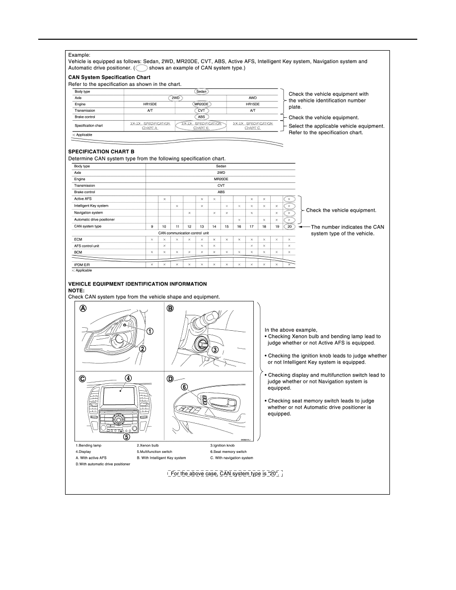
CAN system type is easily checked with the vehicle equipment identification information shown in the chart.

CREATE INTERVIEW SHEET

Fill out the symptom described by the customer, vehicle condition, and CAN system type on the interview
sheet.

JSMIA0530GB

Revision: 2012 October

2013 Murano CrossCabriolet

LAN

DIAGNOSIS AND REPAIR WORKFLOW

LAN-19

< BASIC INSPECTION >

[CAN FUNDAMENTAL]

C

D

E

F

G

H

I

J

K

L

B

A

O

P

N

Interview Sheet (Example)

DETECT THE ROOT CAUSE

CAN diagnosis function of CONSULT detects the root cause.

JSMIA0531GB

Revision: 2012 October

2013 Murano CrossCabriolet

LAN-20

< HOW TO USE THIS MANUAL >

[CAN]

HOW TO USE THIS SECTION

HOW TO USE THIS MANUAL

HOW TO USE THIS SECTION

Information

INFOID:0000000008462768

• “CAN” of LAN Section describes information peculiar to a vehicle and inspection procedures.
• For trouble diagnosis procedure, refer to 

LAN-15, "Trouble Diagnosis Flow Chart"

 of “CAN FUNDAMEN-

TAL”.

Abbreviation List

INFOID:0000000008462769

Unit name abbreviations in CONSULT CAN diagnosis and in this section are as per the following list.

Abbreviation

Unit name

4WD

AWD control unit

A-BAG

Air bag diagnosis sensor unit

ABS

ABS actuator and electric unit (control unit)

ADP

Driver seat control unit

AV

AV control unit

BCM

BCM

C/ROOF

Soft top control unit

DLC

Data link connector

ECM

ECM

HVAC

A/C auto amp.

IPDM-E

IPDM E/R

M&A

Combination meter

STRG

Steering angle sensor

TCM

TCM

Revision: 2012 October

2013 Murano CrossCabriolet

LAN

PRECAUTIONS

LAN-21

< PRECAUTION >

[CAN]

C

D

E

F

G

H

I

J

K

L

B

A

O

P

N

PRECAUTION

PRECAUTIONS

Precaution for Supplemental Restraint System (SRS) "AIR BAG" and "SEAT BELT 
PRE-TENSIONER"

INFOID:0000000008462770

The Supplemental Restraint System such as “AIR BAG” and “SEAT BELT PRE-TENSIONER”, used along
with a front seat belt, helps to reduce the risk or severity of injury to the driver and front passenger for certain
types of collision. This system includes seat belt switch inputs and dual stage front air bag modules. The SRS
system uses the seat belt switches to determine the front air bag deployment, and may only deploy one front
air bag, depending on the severity of a collision and whether the front occupants are belted or unbelted.
Information necessary to service the system safely is included in the “SRS AIR BAG” and “SEAT BELT” of this
Service Manual.

WARNING:

Always observe the following items for preventing accidental activation.
• To avoid rendering the SRS inoperative, which could increase the risk of personal injury or death in

the event of a collision that would result in air bag inflation, all maintenance must be performed by
an authorized NISSAN/INFINITI dealer.

• Improper maintenance, including incorrect removal and installation of the SRS, can lead to personal

injury caused by unintentional activation of the system. For removal of Spiral Cable and Air Bag
Module, see “SRS AIR BAG”.

• Never use electrical test equipment on any circuit related to the SRS unless instructed to in this Ser-

vice Manual. SRS wiring harnesses can be identified by yellow and/or orange harnesses or harness
connectors.

PRECAUTIONS WHEN USING POWER TOOLS (AIR OR ELECTRIC) AND HAMMERS

WARNING:

Always observe the following items for preventing accidental activation.
• When working near the Air Bag Diagnosis Sensor Unit or other Air Bag System sensors with the

ignition ON or engine running, never use air or electric power tools or strike near the sensor(s) with
a hammer. Heavy vibration could activate the sensor(s) and deploy the air bag(s), possibly causing
serious injury.

• When using air or electric power tools or hammers, always switch the ignition OFF, disconnect the

battery, and wait at least 3 minutes before performing any service.

Service Procedure Precautions for Models with a Pop-up Roll Bar

INFOID:0000000008462771

WARNING:

Always observe the following items for preventing accidental activation.
• Risk of passenger injury or death may increase if the pop-up roll bar does not deploy during a roll

over collision. In order to reduce the chance of an incident where the pop-up roll bar is inoperative,
all maintenance must be performed by a NISSAN or INFINITI dealer.

• Before removing and installing the pop-up roll bar component parts and harness, always turn the

ignition switch OFF, disconnect the battery negative terminal, and wait for 3 minutes or more. (The
purpose of this operation is to discharge electricity that is accumulated in the auxiliary power supply
circuit in the air bag diagnosis sensor unit.)

• When repairing, removing, and installing a pop-up roll bar, always refer to SRS AIR BAG and SRS

AIR BAG CONTROL warnings in the Service Manual.

Precaution for Battery Service

INFOID:0000000008462772

Before disconnecting the battery, lower both the driver and passenger windows. This will prevent any interfer-
ence between the window edge and the vehicle when the door is opened/closed. During normal operation, the
window slightly raises and lowers automatically to prevent any window to vehicle interference. The automatic
window function will not work with the battery disconnected.

Precautions for Trouble Diagnosis

INFOID:0000000008462773

CAUTION:

Follow the instructions listed below. Failure to do this may cause damage to parts:

Revision: 2012 October

2013 Murano CrossCabriolet

LAN-22

< PRECAUTION >

[CAN]

PRECAUTIONS

• Never apply 7.0 V or more to the measurement terminal.
• Use a tester with open terminal voltage of 7.0 V or less.
• Turn the ignition switch OFF and disconnect the battery cable from the negative terminal when

checking the harness. 

Precautions for Harness Repair

INFOID:0000000008462774

• Solder the repaired area and wrap tape around the soldered area.

NOTE:
A fray of twisted lines must be within 110 mm (4.33 in).

• Bypass connection is never allowed at the repaired area.

NOTE:
Bypass connection may cause CAN communication error. The
spliced wire becomes separated and the characteristics of twisted
line are lost. 

• Replace the applicable harness as an assembly if error is detected on the shield lines of CAN communica-

tion line.

SKIB8766E

SKIB8767E

Revision: 2012 October

2013 Murano CrossCabriolet

LAN

COMPONENT PARTS

LAN-23

< SYSTEM DESCRIPTION >

[CAN]

C

D

E

F

G

H

I

J

K

L

B

A

O

P

N

SYSTEM DESCRIPTION

COMPONENT PARTS

Component Parts Location

INFOID:0000000008462775

1.

Air bag diagnosis sensor unit

2.

A/C auto amp.

3.

AV control unit 

4.

ABS actuator and electric unit (con-
trol unit)

5.

AWD control unit

6.

TCM

7.

ECM

8.

IPDM E/R

9.

BCM

10. Data link connector

11.

Combination meter

12. Steering angle sensor

13. Driver seat control unit

14. Soft top control unit

JSMIA0748ZZ

Revision: 2012 October

2013 Murano CrossCabriolet

LAN-24

< SYSTEM DESCRIPTION >

[CAN]

SYSTEM

SYSTEM

CAN COMMUNICATION SYSTEM

CAN COMMUNICATION SYSTEM : System Description

INFOID:0000000008462776

SYSTEM DIAGRAM

DESCRIPTION

CAN (Controller Area Network) is a serial communication line for real time application. It is an on-vehicle mul-
tiplex communication line with high data communication speed and excellent error detection ability. Many elec-
tronic control units are equipped onto a vehicle, and each control unit shares information and links with other
control units during operation (not independent). In CAN communication, control units are connected with 2
communication lines (CAN-H line, CAN-L line) allowing a high rate of information transmission with less wiring.
Each control unit transmits/receives data but selectively reads required data only.

Can Communication Signal Generation

• Termination circuits (resistors) are connected across the CAN communication system. When transmitting a

CAN communication signal, each control unit passes a current to the CAN-H line and the current returns to
the CAN-L line.

JSMIA0749GB

JSMIA0450GB

Revision: 2012 October

2013 Murano CrossCabriolet

LAN

SYSTEM

LAN-25

< SYSTEM DESCRIPTION >

[CAN]

C

D

E

F

G

H

I

J

K

L

B

A

O

P

N

• The current flows separately into the termination circuits connected

across the CAN communication system and the termination cir-
cuits drop voltage to generate a potential difference between the
CAN-H line and the CAN-L line.
NOTE:
A signal with no current passage is called “Recessive” and one
with current passage is called “Dominant”.

• The system produces digital signals for signal communications, by

using the potential difference.

The Construction Of Can Communication Signal (Message)

CAN COMMUNICATION LINE

JSMIA0543GB

JSMIA0544ZZ

JSMIA0545ZZ

No.

Message name

Description

1

Start of frame (1 bit)

Start of message.

2

Arbitration of field (11 bit)

Priorities of message-sending are shown when there is a pos-
sibility that multiple messages are sent at the same time.

3

Control field (6 bit)

Signal quantity in data field is shown.

4

Data field (0-64 bit)

Actual signal is shown.

5

CRC field (16 bit)

• The transmitting control unit calculates sending data in ad-

vance and writes the calculated value in a message.

• The receiving control unit calculates received data and judg-

es that the data reception is normal when the calculated val-
ue is the same as the value written in the sent data. 

6

ACK field (2 bit)

The completion of normal reception is sent to the transmitting 
unit.

7

End of frame (7 bit)

End of message.

Revision: 2012 October

2013 Murano CrossCabriolet

LAN-26

< SYSTEM DESCRIPTION >

[CAN]

SYSTEM

The CAN communication line is a twisted pair wire consisting of
strands of CAN-L (1) and CAN-L (2) and has noise immunity.

NOTE:
The CAN communication system has the characteristics of noise-resistant because this system produces dig-
ital signals by using the potential difference between the CAN-H line and the CAN-L line and has the twisted
pair wire structure.
Since the CAN-H line and the CAN-L line are always adjacent to
each other, the same degree of noise occurs, respectively, when a
noise (1) occurs. Although the noise changes the voltage, the poten-
tial difference (2) between the CAN-H line and the CAN-L line is
insensitive to noise. Therefore, noise-resistant signals can be
obtained.

CAN SIGNAL COMMUNICATIONS

Each control unit of the CAN communication system transmits signals through the CAN communication con-
trol circuit included in the control unit and receives only necessary signals from each control unit to perform
various kinds of control.
• Example: Transmitted signals

JSMIA0382ZZ

JSMIA0383ZZ

JSMIA0576GB

Revision: 2012 October

2013 Murano CrossCabriolet

LAN

SYSTEM

LAN-27

< SYSTEM DESCRIPTION >

[CAN]

C

D

E

F

G

H

I

J

K

L

B

A

O

P

N

• Example: Received signals

NOTE:
The above signal names and signal communications are provided for reference purposes. For CAN communi-
cations signals of this vehicle, refer to 

LAN-28, "CAN COMMUNICATION SYSTEM : CAN Communication

Signal Chart"

.

CAN COMMUNICATION SYSTEM : CAN Communication Control Circuit

INFOID:0000000008462777

CAN communication control circuit is incorporated into the control unit and transmits/receives CAN communi-
cation signals.

JSMIA0577GB

JSMIA0453GB

Component

System description

CAN controller

It controls CAN communication signal transmission and reception, error detection, etc.

Transceiver IC

It converts digital signal into CAN communication signal, and CAN communication signal into digital 
signal.

Revision: 2012 October

2013 Murano CrossCabriolet

LAN-28

< SYSTEM DESCRIPTION >

[CAN]

SYSTEM

*: These are the only control units wired with both ends of CAN communication system.

CAN COMMUNICATION SYSTEM : CAN System Specification Chart

INFOID:0000000008462778

Determine CAN system type from the following specification chart.
NOTE:
Refer to 

LAN-15, "Trouble Diagnosis Procedure"

 for how to use CAN system specification chart.

CAN COMMUNICATION SYSTEM : CAN Communication Signal Chart

INFOID:0000000008462779

Refer to 

LAN-14, "How to Use CAN Communication Signal Chart"

 for how to use CAN communication signal

chart.
NOTE:
Refer to 

LAN-20, "Abbreviation List"

 for the abbreviations of the connecting units.

T: Transmit

R: Receive

Noise filter

It eliminates noise of CAN communication signal.

Termination circuit

*

(Resistance of approx. 120 

Ω

)

Generates a potential difference between CAN-H and CAN-L.

Component

System description

Body type

Convertible

Axle

AWD

Engine

VQ35DE

Transmission

CVT

Brake control

VDC

CAN system type

1

Signal name

EC

M

ADP

C/ROO

F

4WD

AV

HV

AC

M&A

A-BAG

BC

M

ST

R

G

ABS

TCM

IP

DM-E

A/C compressor request signal

T

R

Accelerator pedal position signal 

T

R

R

R

ASCD CRUISE indicator signal

T

R

ASCD operation signal

T

R

ASCD SET indicator signal

T

R

Closed throttle position signal

T

R

Cooling fan speed request signal

T

R

Engine and CVT integrated control signal

T

R

R

T

Engine coolant temperature signal

T

R

R

R

Engine speed signal

T

R

R

R

R

Engine status signal

T

R

R

Fuel consumption monitor signal

T

R

R

Fuel filler cap warning display signal

T

R

Malfunctioning indicator lamp signal

T

R

Power generation command value signal

T

R

System setting signal

T

R

R

T

R

R

T

Meter display signal

T

R

R

T

Revision: 2012 October

2013 Murano CrossCabriolet

LAN

SYSTEM

LAN-29

< SYSTEM DESCRIPTION >

[CAN]

C

D

E

F

G

H

I

J

K

L

B

A

O

P

N

Roof operation signal

T

R

Roof status signal

T

R

Tonneau board status signal

T

R

AWD LOCK indicator lamp signal

T

R

AWD malfunction signal

T

R

AWD signal

T

R

AWD warning lamp signal

T

R

A/C switch/indicator signal

T

R

R

T

A/C switch operation signal

T

R

Rear window defogger switch signal

T

R

Voice recognition signal

T

R

A/C switch signal

R

T

T

Blower fan motor switch signal

R

T

T

Brake fluid level switch signal

T

R

Distance to empty signal

R

T

Fuel filler cap warning reset signal

R

T

Fuel level low warning signal

R

T

Fuel level sensor signal

R

T

Odometer signal

T

R

Overdrive control switch signal

T

R

Parking brake switch signal

R

T

Seat belt buckle switch signal

T

R

Sleep-ready signal

T

R

R

T

Vehicle speed signal

R

R

R

R

T

R

R

R

R

R

R

R

R

T

Wake up signal

T

R

Pop-up roll bar malfunction signal

R

T

Pop-up roll bar operation signal

R

T

Buzzer output signal

R

T

Door switch signal

R

R

R

T

R

Door unlock signal

R

T

Front fog light request signal

T

R

Front wiper request signal

T

R

High beam request signal

R

T

R

Horn reminder signal

T

R

Ignition switch ACC signal

R

R

T

Ignition switch ON signal

R

R

T

R

R

T

Interlock/PNP switch signal

T

R

R

T

Key ID signal

R

T

Signal name

ECM

ADP

C/RO

OF

4WD

AV

HV

AC

M&A

A-B

AG

BCM

STRG

ABS

TCM

IPDM

-E

Revision: 2012 October

2013 Murano CrossCabriolet

LAN-30

< SYSTEM DESCRIPTION >

[CAN]

SYSTEM

Key switch signal

R

T

Key warning lamp signal

R

T

Low beam request signal

T

R

Low tire pressure warning lamp signal

R

T

Oil pressure switch signal

R

T

R

T

Position light request signal

R

T

R

Rear window defogger control signal

T

R

R

R

T

Shipping mode status signal

R

T

Sleep wake up signal

R

R

R

T

R

Starter control relay signal

T

R

Starter relay status signal

T

R

R

T

Starting mode signal

R

R

T

Stop lamp switch signal

T

R

R

T

Theft warning horn request signal

T

R

TPMS malfunction warning lamp signal

R

T

Trunk switch signal

R

T

Turn indicator signal

R

T

Steering angle sensor signal

R

R

T

R

ABS operation signal 

T

R

ABS warning lamp signal

R

T

Brake warning lamp signal

R

T

Decel G sensor signal

R

T

Side G sensor signal

R

T

VDC OFF indicator lamp signal

R

T

VDC warning lamp signal

R

T

Yaw rate sensor signal

R

T

Current gear position signal

R

T

CVT position indicator signal

R

R

R

T

CVT self-diagnosis signal

R

T

Input shaft revolution signal

R

T

N range signal

R

R

T

OD OFF indicator signal

R

T

Output shaft revolution signal

R

T

P range signal

R

R

R

T

R range signal

R

T

Shift position signal

R

R

T

A/C compressor feedback signal

R

R

T

Detention switch signal

R

T

Front wiper stop position signal

R

T

Signal name

ECM

ADP

C/RO

OF

4WD

AV

HV

AC

M&A

A-B

AG

BCM

STRG

ABS

TCM

IPDM

-E

Revision: 2012 October

2013 Murano CrossCabriolet

LAN

SYSTEM

LAN-31

< SYSTEM DESCRIPTION >

[CAN]

C

D

E

F

G

H

I

J

K

L

B

A

O

P

N

High beam status signal

R

T

Low beam status signal

R

T

Push-button ignition switch status signal

R

T

Signal name

ECM

ADP

C/RO

OF

4WD

AV

HV

AC

M&A

A-B

AG

BCM

STRG

ABS

TCM

IPDM

-E

Revision: 2012 October

2013 Murano CrossCabriolet

LAN-32

< WIRING DIAGRAM >

[CAN]

CAN SYSTEM

WIRING DIAGRAM

CAN SYSTEM

Wiring Diagram

INFOID:0000000008462780

For connector terminal arrangements, harness layouts, and alphabets in a 

 (option abbreviation; if not

described in wiring diagram), refer to 

GI-12, "Connector Information"

.

JRMWD5069GB

Revision: 2012 October

2013 Murano CrossCabriolet

LAN

CAN SYSTEM

LAN-33

< WIRING DIAGRAM >

[CAN]

C

D

E

F

G

H

I

J

K

L

B

A

O

P

N

JRMWD5070GB

Revision: 2012 October

2013 Murano CrossCabriolet


Content      ..     54      55      56      57     ..