Murano Cross Cabriolet Z51 (2013 year). Manual - part 31


  Index      Manuals     Murano Cross Cabriolet Z51 (2013 year) - Service and Repair Manual


Search            copyright infringement  


Content      ..     29      30      31      32     ..


Murano Cross Cabriolet Z51 (2013 year). Manual - part 31


EXL-14

< SYSTEM DESCRIPTION >

[XENON TYPE]

SYSTEM

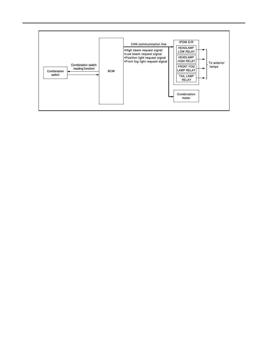
EXTERIOR LAMP BATTERY SAVER SYSTEM : System Diagram

INFOID:0000000008460279

EXTERIOR LAMP BATTERY SAVER SYSTEM : System Description

INFOID:0000000008460280

OUTLINE

• Exterior lamp battery saver system is controlled by each function of BCM and IPDM E/R.

Control by BCM

- Combination switch reading function
- Headlamp control function
- Exterior lamp battery saver function

Control by IPDM E/R

- Relay control function
• BCM turns the exterior lamp* OFF after a period of time to prevent the battery from over-discharge when the

ignition switch is turned OFF with the exterior lamp ON.

*: Headlamp (LO/HI), parking lamp, side marker lamp, tail lamp, license plate lamp and front fog lamp.

EXTERIOR LAMP BATTERY SAVER ACTIVATION

BCM activates the timer and turns the exterior lamp OFF 45 seconds after the ignition switch is turned from
ON 

 OFF with the exterior lamps ON. 

NOTE:
• Headlamp control function turns the exterior lamps ON normally when the ignition switch is turned ACC or

ON (both before and after the exterior lamp battery saver is turned OFF).

• The timer starts at the time that the lighting switch is turned from OFF 

 1ST or 2ND with the exterior lamp

OFF.

JPLIA1037GB

Revision: 2012 October

2013 Murano CrossCabriolet

DIAGNOSIS SYSTEM (BCM)

EXL-15

< SYSTEM DESCRIPTION >

[XENON TYPE]

C

D

E

F

G

H

I

J

K

M

A

B

EXL

N

O

P

DIAGNOSIS SYSTEM (BCM)

COMMON ITEM

COMMON ITEM : CONSULT Function (BCM - COMMON ITEM)

INFOID:0000000008954729

APPLICATION ITEM

CONSULT performs the following functions via CAN communication with BCM.

SYSTEM APPLICATION

BCM can perform the following functions for each system.
NOTE:
It can perform the diagnosis modes except the following for all sub system selection items.

×

: Applicable item

NOTE:

*: This item is displayed, but is not used. 

FREEZE FRAME DATA (FFD)

The BCM records the following vehicle condition at the time a particular DTC is detected, and displays on
CONSULT.

Diagnosis mode

Function Description

Work Support

Changes the setting for each system function.

Self Diagnostic Result

Displays the diagnosis results judged by BCM.

CAN Diag Support Monitor

Monitors the reception status of CAN communication viewed from BCM.

Data Monitor

The BCM input/output signals are displayed.

Active Test

The signals used to activate each device are forcibly supplied from BCM.

Ecu Identification

The BCM part number is displayed.

Configuration

• Read and save the vehicle specification.
• Write the vehicle specification when replacing BCM.

System

Sub system selection item

Diagnosis mode

Work Support

Data Monitor

Active Test

Door lock

DOOR LOCK

×

×

×

Rear window defogger

REAR DEFOGGER

×

×

Warning chime

BUZZER

×

×

Interior room lamp timer

INT LAMP

×

×

×

Exterior lamp

HEAD LAMP

×

×

×

Wiper and washer

WIPER

×

×

×

Turn signal and hazard warning lamps

FLASHER

×

×

×

AIR CONDITONER*

• Intelligent Key system
• Engine start system

INTELLIGENT KEY

×

×

×

Combination switch

COMB SW

×

Body control system

BCM

×

NVIS - NATS

IMMU

×

×

Interior room lamp battery saver

BATTERY SAVER

×

×

×

Trunk lid opener system

TRUNK

×

×

Vehicle security system

THEFT ALM

×

×

×

RAP system

RETAINED PWR

×

Signal buffer system

SIGNAL BUFFER

×

×

TPMS

AIR PRESSURE MONITOR

×

×

×

Revision: 2012 October

2013 Murano CrossCabriolet

EXL-16

< SYSTEM DESCRIPTION >

[XENON TYPE]

DIAGNOSIS SYSTEM (BCM)

NOTE:

*: Power supply position shifts to “LOCK” from “OFF”, when ignition switch is in the OFF position, selector lever is in the P position, and
any of the following conditions are met.

• Closing door

• Opening door

• Door is locked using door request switch

• Door is locked using Intelligent Key

The power supply position shifts to “ACC” when the push-button ignition switch (push switch) is pushed at “LOCK”.

HEADLAMP

HEADLAMP : CONSULT Function (BCM - HEAD LAMP)

INFOID:0000000008460282

WORK SUPPORT

CONSULT screen item

Indication/Unit

Description

Vehicle Speed

km/h

Vehicle speed of the moment a particular DTC is detected

Odo/Trip Meter

km

Total mileage (Odometer value) of the moment a particular DTC is detected

Vehicle Condition

SLEEP>LOCK

Power position status of 
the moment a particular 
DTC is detected

While turning BCM status from low power consumption mode to 
normal mode (Power supply position is “LOCK”*)

SLEEP>OFF

While turning BCM status from low power consumption mode to 
normal mode (Power supply position is “OFF”.)

LOCK>ACC

While turning power supply position from “LOCK” to “ACC”

ACC>ON

While turning power supply position from “ACC” to “IGN”

RUN>ACC

While turning power supply position from “RUN” to “ACC” (Vehicle 
is stopping and selector lever is except P position.)

CRANK>RUN

While turning power supply position from “CRANKING” to “RUN” 
(From cranking up the engine to run it)

RUN>URGENT

While turning power supply position from “RUN“ to “ACC” (Emer-
gency stop operation)

ACC>OFF

While turning power supply position from “ACC” to “OFF”

OFF>LOCK

While turning power supply position from “OFF” to “LOCK”*

OFF>ACC

While turning power supply position from “OFF” to “ACC”

ON>CRANK

While turning power supply position from “IGN” to “CRANKING”

OFF>SLEEP

While turning BCM status from normal mode (Power supply posi-
tion is “OFF”.) to low power consumption mode

LOCK>SLEEP

While turning BCM status from normal mode (Power supply posi-
tion is “LOCK”*) to low power consumption mode

LOCK

Power supply position is “LOCK”*

OFF

Power supply position is “OFF” (Ignition switch OFF)

ACC

Power supply position is “ACC” (Ignition switch ACC)

ON

Power supply position is “IGN” (Ignition switch ON with engine 
stopped)

ENGINE RUN

Power supply position is “RUN” (Ignition switch ON with engine 
running)

CRANKING

Power supply position is “CRANKING” (At engine cranking)

IGN Counter

0 - 39

The number of times that ignition switch is turned ON after DTC is detected
• The number is 0 when a malfunction is detected now.
• The number increases like 1 

 2 

 3...38 

 39 after returning to the normal condition 

whenever ignition switch OFF 

 ON.

• The number is fixed to 39 until the self-diagnosis results are erased if it is over 39.

Revision: 2012 October

2013 Murano CrossCabriolet

DIAGNOSIS SYSTEM (BCM)

EXL-17

< SYSTEM DESCRIPTION >

[XENON TYPE]

C

D

E

F

G

H

I

J

K

M

A

B

EXL

N

O

P

*: Factory setting

DATA MONITOR

NOTE:
The following table includes information (items) inapplicable to this vehicle. For information (items) applicable
to this vehicle, refer to CONSULT display items.

Service item

Setting item

Setting

CUSTOM A/LIGHT SET-
TING

MODE 1*

Normal

MODE 2

More sensitive setting than normal setting (Turns ON earlier than normal operation.)

MODE 3

More sensitive setting than MODE 2 (Turns ON earlier than MODE 2.)

MODE 4

Less sensitive setting than normal setting (Turns ON later than normal operation.)

BATTERY SAVER SET

On*

With the exterior lamp battery saver function

Off

Without the exterior lamp battery saver function

ILL DELAY SET

MODE 1*

45 sec.

Sets delay timer function timer operation time.
(All doors closed)

MODE 2

Without the func-
tion

MODE 3

30 sec.

MODE 4

60 sec.

MODE 5

90 sec.

MODE 6

120 sec.

MODE 7

150 sec.

MODE 8

180 sec.

Monitor item

[Unit]

Description

PUSH SW
[On/Off]

The switch status input from push-button ignition switch

ENGINE STATE
[Stop/Stall/Crank/Run]

The engine status received from ECM via CAN communication

VEH SPEED 1
[km/h]

The value of the vehicle speed received from combination meter via CAN communi-
cation

KEY SW-SLOT
[On/Off]

Key switch status input from key slot

TURN SIGNAL R
[On/Off]

Each switch status that BCM detects from the combination switch reading function

TURN SIGNAL L
[On/Off]

TAIL LAMP SW
[On/Off]

HI BEAM SW
[On/Off]

HEAD LAMP SW1
[On/Off]

HEAD LAMP SW2
[On/Off]

PASSING SW
[On/Off]

AUTO LIGHT SW
[On/Off]

FR FOG SW
[On/Off]

Revision: 2012 October

2013 Murano CrossCabriolet

EXL-18

< SYSTEM DESCRIPTION >

[XENON TYPE]

DIAGNOSIS SYSTEM (BCM)

ACTIVE TEST

FLASHER

FLASHER : CONSULT Function (BCM - FLASHER)

INFOID:0000000008460283

WORK SUPPORT

*: Factory setting

DATA MONITOR

RR FOG SW
[On/Off]

NOTE:
The item is indicated, but not monitored.

DOOR SW-DR
[On/Off]

The switch status input from front door switch (driver side)

DOOR SW-AS
[On/Off]

The switch status input from front door switch (passenger side)

DOOR SW-RR
[On/Off]

NOTE:
The item is indicated, but not monitored.

DOOR SW-RL
[On/Off]

NOTE:
The item is indicated, but not monitored.

DOOR SW-BK
[On/Off]

NOTE:
The item is indicated, but not monitored.

OPTICAL SENSOR
[V]

The value of exterior brightness voltage input from the optical sensor 

Monitor item

[Unit]

Description

Test item

Operation

Description

TAIL LAMP

On

Transmits the position light request signal to IPDM E/R via CAN commu-
nication to turn the tail lamp ON.

Off

Stops the position light request signal transmission.

HEAD LAMP

Hi

Transmits the high beam request signal via CAN communication to turn 
the headlamp (HI).

Low

Transmits the low beam request signal via CAN communication to turn 
the headlamp (LO).

Off

Stops the high & low beam request signal transmission.

FR FOG LAMP

On

Transmits the front fog light request signal to IPDM E/R via CAN commu-
nication to turn the front fog lamp ON.

Off

Stops the front fog light request signal transmission.

RR FOG LAMP

On

NOTE:
The item is indicated, but cannot be tested.

Off

CORNERING LAMP

RH

NOTE:
The item is indicated, but cannot be tested.

LH

Off

ILL DIM SIGNAL

On

NOTE:
The item is indicated, but cannot be tested.

Off

Service item

Setting item

Setting

HAZARD ANSWER 
BACK

Lock Only*

With locking only

Sets the hazard warning lamp answer back function 
when the door is lock/unlock with the request switch or 
the key fob.

Unlk Only

With unlocking only

Lock/Unlk

With locking/unlocking

Off

Without the function

Revision: 2012 October

2013 Murano CrossCabriolet

DIAGNOSIS SYSTEM (BCM)

EXL-19

< SYSTEM DESCRIPTION >

[XENON TYPE]

C

D

E

F

G

H

I

J

K

M

A

B

EXL

N

O

P

NOTE:
The following table includes information (items) inapplicable to this vehicle. For information (items) applicable
to this vehicle, refer to CONSULT display items.

ACTIVE TEST

Monitor item

[Unit]

Description

REQ SW-DR
[On/Off]

The switch status input from the door request switch (driver side)

REQ SW-AS
[On/Off]

The switch status input from the door request switch (passenger side)

PUSH SW
[On/Off]

The switch status input from the push-button ignition switch

TURN SIGNAL R
[On/Off]

Each switch status that BCM detects from the combination switch reading function

TURN SIGNAL L
[On/Off]

HAZARD SW
[On/Off]

The switch status input from the hazard switch

RKE-LOCK
[On/Off]

Lock signal status received from the remote keyless entry receiver

RKE-UNLOCK
[On/Off]

Unlock signal status received from the remote keyless entry receiver

RKE-PANIC
[On/Off]

Panic alarm signal status received from the remote keyless entry receiver

Test item

Operation

Description

FLASHER

RH

Outputs the voltage to blink the right side turn signal lamps.

LH

Outputs the voltage to blink the left side turn signal lamps.

Off

Stops the voltage to turn the turn signal lamps OFF.

Revision: 2012 October

2013 Murano CrossCabriolet

EXL-20

< SYSTEM DESCRIPTION >

[XENON TYPE]

DIAGNOSIS SYSTEM (IPDM E/R)

DIAGNOSIS SYSTEM (IPDM E/R)

Diagnosis Description

INFOID:0000000008954740

AUTO ACTIVE TEST

Description

In auto active test mode, the IPDM E/R sends a drive signal to the following systems to check their operation.
• Oil pressure warning lamp
• Front wiper (LO, HI)
• Parking lamp
• License plate lamp
• Side maker lamp
• Tail lamp
• Front fog lamp
• Headlamp (LO, HI)
• A/C compressor (magnet clutch)
• Cooling fan

Operation Procedure

NOTE:
Never perform auto active test in the following conditions.
• CONSULT is connected
• Passenger door is open

1.

Close the hood and lift the wiper arms from the windshield. (Prevent windshield damage due to wiper
operation)
NOTE:
When auto active test is performed with hood opened, sprinkle water on windshield beforehand.

2.

Turn the ignition switch OFF.

3.

Turn the ignition switch ON, and within 20 seconds, press the front door switch (driver side) 10 times.
Then turn the ignition switch OFF.

4.

Turn the ignition switch ON within 10 seconds. After that the horn sounds once and the auto active test
starts.

5.

After a series of the following operations is repeated 3 times, auto active test is completed.

NOTE:
• When auto active test has to be cancelled halfway through test, turn the ignition switch OFF.
• When auto active test is not activated, door switch may be the cause. Check door switch. Refer to 

DLK-55,

"Component Function Check"

.

Inspection in Auto Active Test Mode

When auto active test mode is actuated, the following 6 steps are repeated 3 times.

Operation 
sequence

Inspection location

Operation

1

Oil pressure warning lamp

Blinks continuously during operation of auto active test 

2

Front wiper motor

LO for 5 seconds 

 HI for 5 seconds

3

• Parking  lamp
• License plate lamp
• Side maker lamp
• Tail lamp
• Front fog lamp

10 seconds

4

Headlamp

LO 

 HI 5 times

5

A/C compressor (magnet clutch)

ON 

 OFF 5 times

6

Cooling fan

LO for 5 seconds 

 MID for 3 seconds 

 HI for 2 seconds

Revision: 2012 October

2013 Murano CrossCabriolet

DIAGNOSIS SYSTEM (IPDM E/R)

EXL-21

< SYSTEM DESCRIPTION >

[XENON TYPE]

C

D

E

F

G

H

I

J

K

M

A

B

EXL

N

O

P

Concept of auto active test

• IPDM E/R starts the auto active test with the door switch signals transmitted by BCM via CAN communica-

tion. Therefore, the CAN communication line between IPDM E/R and BCM is considered normal if the auto
active test starts successfully.

• The auto active test facilitates troubleshooting if any systems controlled by IPDM E/R cannot be operated.

Diagnosis chart in auto active test mode

JMMIA0836GB

Symptom

Inspection contents

Possible cause

Any of the following components do not operate

• Parking lamp
• License plate lamp
• Side maker lamp
• Tail  lamp
• Front  fog  lamp
• Headlamp (HI, LO)
• Front motor wiper

Perform auto active test.
Does the applicable system 
operate?

YES

BCM signal input circuit

NO

• Lamp or motor
• Lamp or motor ground circuit
• Harness or connector between 

IPDM E/R and applicable system

• IPDM E/R

A/C compressor does not operate

Perform auto active test.
Does the magnet clutch oper-
ate?

YES

• A/C amp. signal input circuit
• CAN communication signal between 

A/C amp. and ECM

• CAN communication signal between 

ECM and IPDM E/R

NO

• Magnet clutch
• Harness or connector between 

IPDM E/R and magnet clutch

• IPDM E/R

Oil pressure warning lamp does not operate

Perform auto active test.
Does the oil pressure warning 
lamp blink?

YES

• Harness or connector between 

IPDM E/R and oil pressure switch

• Oil pressure switch
• IPDM E/R

NO

• CAN communication signal between 

IPDM E/R and BCM

• CAN communication signal between 

BCM and combination meter

• Combination meter

Revision: 2012 October

2013 Murano CrossCabriolet

EXL-22

< SYSTEM DESCRIPTION >

[XENON TYPE]

DIAGNOSIS SYSTEM (IPDM E/R)

CONSULT Function (IPDM E/R)

INFOID:0000000008954741

APPLICATION ITEM

CONSULT performs the following functions via CAN communication with IPDM E/R.

SELF DIAGNOSTIC RESULT

Refer to 

PCS-23, "DTC Index"

.

DATA MONITOR

NOTE:
The following table includes information (items) inapplicable to this vehicle. For information (items) applicable
to this vehicle, refer to CONSULT display items.

Cooling fan does not operate

Perform auto active test.
Does the cooling fan operate?

YES

• ECM signal input circuit
• CAN communication signal between 

ECM and IPDM E/R

NO

• Harness or connector between 

IPDM E/R and cooling fan motor

• Harness or connector between 

IPDM E/R and cooling fan relay

• Cooling fan motor
• Cooling fan relay
• IPDM  E/R

Symptom

Inspection contents

Possible cause

Diagnosis mode

Description

Ecu Identification

Allows confirmation of IPDM E/R part number.

Self Diagnostic Result

Displays the diagnosis results judged by IPDM E/R.

Data Monitor

Displays the real-time input/output data from IPDM E/R input/output data.

Active Test

IPDM E/R can provide a drive signal to electronic components to check their operations.

CAN Diag Support Monitor

The results of transmit/receive diagnosis of CAN communication can be read.

Monitor Item

[Unit]

MAIN SIG-

NALS

Description

MOTOR FAN REQ
[1/2/3/4]

×

Displays the value of the cooling fan speed request signal received from ECM via 
CAN communication.

AC COMP REQ
[Off/On]

×

Displays the status of the A/C compressor request signal received from ECM via 
CAN communication.

TAIL&CLR REQ
[Off/On]

×

Displays the status of the position light request signal received from BCM via CAN 
communication.

HL LO REQ
[Off/On]

×

Displays the status of the low beam request signal received from BCM via CAN 
communication.

HL HI REQ
[Off/On]

×

Displays the status of the high beam request signal received from BCM via CAN 
communication.

FR FOG REQ
[Off/On]

×

Displays the status of the front fog light request signal received from BCM via 
CAN communication.

FR WIP REQ
[Stop/1LOW/Low/Hi]

×

Displays the status of the front wiper request signal received from BCM via CAN 
communication.

WIP AUTO STOP
[STOP P/ACT P]

×

Displays the status of the front wiper auto stop signal judged by IPDM E/R.

WIP PROT
[Off/BLOCK]

×

Displays the status of the front wiper fail-safe operation judged by IPDM E/R.

IGN RLY1 -REQ
[Off/On]

Displays the status of the ignition switch ON signal received from BCM via CAN 
communication.

IGN RLY
[Off/On]

×

Displays the status of the ignition relay judged by IPDM E/R.

Revision: 2012 October

2013 Murano CrossCabriolet

DIAGNOSIS SYSTEM (IPDM E/R)

EXL-23

< SYSTEM DESCRIPTION >

[XENON TYPE]

C

D

E

F

G

H

I

J

K

M

A

B

EXL

N

O

P

ACTIVE TEST

PUSH SW
[Off/On]

Displays the status of the push-button ignition switch judged by IPDM E/R.

INTER/NP SW
[Off/On]

Displays the status of the shift position judged by IPDM E/R.

ST RLY CONT
[Off/On]

Displays the status of the starter relay status signal received from BCM via CAN 
communication.

IHBT RLY -REQ
[Off/On]

Displays the status of the starter control relay signal received from BCM via CAN 
communication.

ST/INHI RLY
[Off/ ST ON/INHI ON/UNKWN]

Displays the status of the starter relay and starter control relay judged by IPDM 
E/R.

DETENT SW
[Off/On]

Displays the status of the CVT shift selector (detention switch) judged by IPDM E/
R.

S/L RLY -REQ
[Off/On]

NOTE:
The item is indicated, but not monitored.

S/L STATE
[LOCK/UNLOCK/UNKWN]

NOTE:
The item is indicated, but not monitored.

DTRL REQ
[Off/On]

NOTE:
The item is indicated, but not monitored.

OIL P SW
[Open/Close]

Displays the status of the oil pressure switch judged by IPDM E/R.

HOOD SW
[Off/On]

NOTE:
The item is indicated, but not monitored.

HL WASHER REQ
[Off/On]

NOTE:
The item is indicated, but not monitored.

THFT HRN REQ
[Off/On]

Displays the status of the theft warning horn request signal received from BCM 
via CAN communication.

HORN CHIRP
[Off/On]

Displays the status of the horn reminder signal received from BCM via CAN com-
munication.

CRNRNG LMP REQ
[Off/On]

NOTE:
The item is indicated, but not monitored.

Monitor Item

[Unit]

MAIN SIG-

NALS

Description

Test item

Operation

Description

CORNERING LAMP

Off

NOTE:
The item is indicated, but cannot be tested.

LH

RH

HORN

On

Operates horn relay for 20 ms.

FRONT WIPER

Off

OFF

Lo

Operates the front wiper relay.

Hi

Operates the front wiper relay and front wiper high relay.

MOTOR FAN

1

OFF

2

Operates the cooling fan relay-1.

3

Operates the cooling fan relay-2.

4

Operates the cooling fan relay-2 and cooling fan relay-3.

HEAD LAMP WASHER

On

NOTE:
The item is indicated, but cannot be tested.

Revision: 2012 October

2013 Murano CrossCabriolet

EXL-24

< SYSTEM DESCRIPTION >

[XENON TYPE]

DIAGNOSIS SYSTEM (IPDM E/R)

EXTERNAL LAMPS

Off

OFF

TAIL

Operates the tail lamp relay.

Lo

Operates the headlamp low relay.

Hi

Operates the headlamp low relay and ON/OFF the headlamp high relay at 1 sec-
ond intervals.

Fog

Operates the front fog lamp relay.

Test item

Operation

Description

Revision: 2012 October

2013 Murano CrossCabriolet

BCM, IPDM E/R

EXL-25

< ECU DIAGNOSIS INFORMATION >

[XENON TYPE]

C

D

E

F

G

H

I

J

K

M

A

B

EXL

N

O

P

ECU DIAGNOSIS INFORMATION

BCM, IPDM E/R

List of ECU Reference

INFOID:0000000008460286

ECU

Reference

BCM

BCS-32, "Reference Value"

BCS-54, "Fail-safe"

BCS-54, "DTC Inspection Priority Chart"

BCS-55, "DTC Index"

IPDM E/R

PCS-15, "Reference Value"

PCS-21, "Fail-safe"

PCS-23, "DTC Index"

Revision: 2012 October

2013 Murano CrossCabriolet

EXL-26

< WIRING DIAGRAM >

[XENON TYPE]

HEADLAMP SYSTEM

WIRING DIAGRAM

HEADLAMP SYSTEM

Wiring Diagram 

INFOID:0000000008460287

For connector terminal arrangements, harness layouts, and alphabets in a 

 (option abbreviation; if not

described in wiring diagram), refer to 

GI-12, "Connector Information"

.

JCLWA5273GB

Revision: 2012 October

2013 Murano CrossCabriolet

AUTO LIGHT SYSTEM

EXL-27

< WIRING DIAGRAM >

[XENON TYPE]

C

D

E

F

G

H

I

J

K

M

A

B

EXL

N

O

P

AUTO LIGHT SYSTEM

Wiring Diagram 

INFOID:0000000008460288

For connector terminal arrangements, harness layouts, and alphabets in a 

 (option abbreviation; if not

described in wiring diagram), refer to 

GI-12, "Connector Information"

.

JRLWC2940GB

Revision: 2012 October

2013 Murano CrossCabriolet

EXL-28

< WIRING DIAGRAM >

[XENON TYPE]

FRONT FOG LAMP SYSTEM

FRONT FOG LAMP SYSTEM

Wiring Diagram

INFOID:0000000008460289

For connector terminal arrangements, harness layouts, and alphabets in a 

 (option abbreviation; if not

described in wiring diagram), refer to 

GI-12, "Connector Information"

.

JRLWC1211GB

Revision: 2012 October

2013 Murano CrossCabriolet

TURN SIGNAL AND HAZARD WARNING LAMP SYSTEM

EXL-29

< WIRING DIAGRAM >

[XENON TYPE]

C

D

E

F

G

H

I

J

K

M

A

B

EXL

N

O

P

TURN SIGNAL AND HAZARD WARNING LAMP SYSTEM

Wiring Diagram 

INFOID:0000000008460290

For connector terminal arrangements, harness layouts, and alphabets in a 

 (option abbreviation; if not

described in wiring diagram), refer to 

GI-12, "Connector Information"

.

JCLWA5287GB

Revision: 2012 October

2013 Murano CrossCabriolet


Content      ..     29      30      31      32     ..