Murano Cross Cabriolet Z51 (2013 year). Manual - part 27


  Index      Manuals     Murano Cross Cabriolet Z51 (2013 year) - Service and Repair Manual


Search            copyright infringement  


Content      ..     25      26      27      28     ..


Murano Cross Cabriolet Z51 (2013 year). Manual - part 27


CO-20

< REMOVAL AND INSTALLATION >

WATER PUMP

5.

Remove reservoir tank of radiator. Refer to 

CO-13, "Exploded View"

.

6.

Remove reservoir tank of power steering oil pump with piping connected, and move it to aside. Refer to

ST-53, "Exploded View"

.

7.

Support oil pan (lower) bottom with transmission jack.

8.

Remove engine mounting insulator (RH), engine mounting bracket (RH) and upper torque rod. Refer to

EM-67, "Exploded View"

.

9.

Remove water drain plug (front) on water pump side of cylinder block to drain engine coolant from engine
inside.

10. Remove valve timing control cover (bank 1) and water pump cover from front timing chain case.

• Use the seal cutter [SST: KV10111100 (J-37228)] to cut liquid gasket for removal.

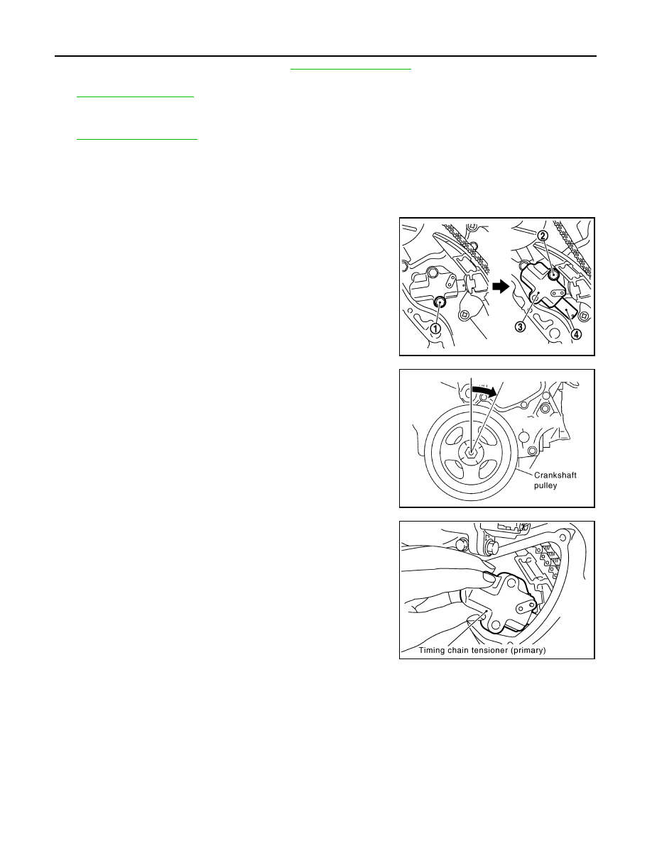
11. Remove timing chain tensioner (primary) as follows:

a.

Remove lower mounting bolt (1).

CAUTION:

Never drop mounting bolt inside timing chain case.

b.

Loosen upper mounting bolt (2) slowly, and then turn chain ten-
sioner (primary) (3) on the mounting bolt so that plunger (4) is
fully expanded.
NOTE:
Even if plunger is fully expanded, it is not dropped from the body
of timing chain tensioner (primary).

c.

Turn crankshaft pulley clockwise so that timing chain on the tim-
ing chain tensioner (primary) side is loose.

d.

Remove upper mounting bolt, and then remove timing chain ten-
sioner (primary).

CAUTION:

Never drop mounting bolt inside timing chain case.

12. Remove water pump as follows:

JPBIA0085ZZ

PBIC4820E

PBIC3576E

Revision: 2012 October

2013 Murano CrossCabriolet

WATER PUMP

CO-21

< REMOVAL AND INSTALLATION >

C

D

E

F

G

H

I

J

K

L

M

A

CO

N

P

O

a.

Remove three water pump mounting bolts. Secure a gap
between water pump gear and timing chain, by turning crank-
shaft pulley counterclockwise until timing chain looseness on
water pump sprocket becomes maximum. 

b.

Screw M8 bolts [pitch: 1.25 mm (0.0492 in) length: approxi-
mately 50 mm (1.97 in)]  into  water  pumps  upper  and  lower
mounting bolt holes until they reach timing chain case. Then,
alternately tighten each bolt for a half turn, and pull out water
pump.

CAUTION:

• Pull straight out while preventing vane from contacting

socket in installation area.

• Remove water pump without causing sprocket to contact

timing chain.

c.

Remove M8 bolts and O-rings from water pump.

CAUTION:

Never disassemble water pump.

INSTALLATION

CAUTION:

Do not reuse O-rings.

1.

Install new O-rings to water pump.

CAUTION:

Do not reuse O-rings.
• Apply engine oil and engine coolant to O-rings as shown in the

figure.

• Locate O-ring with white paint mark to engine front side.

2.

Install water pump.

CAUTION:

Never allow cylinder block to nip O-rings when installing
water pump.
• Check that timing chain and water pump sprocket are

engaged.

• Insert water pump by tightening mounting bolts alternately and

evenly.

3.

Install timing chain tensioner (primary) as follows:

PBIC1193E

JLC357B

PBIC1397E

SLC031B

Revision: 2012 October

2013 Murano CrossCabriolet

CO-22

< REMOVAL AND INSTALLATION >

WATER PUMP

a.

Turn crankshaft pulley clockwise so that timing chain on the tim-
ing chain tensioner (primary) side is loose.

b.

Pull plunger stopper tab (A) up (or turn lever downward) so as to
remove plunger stopper tab from the ratchet of plunger (D).
NOTE:
Plunger stopper tab and lever (C) are synchronized.

c.

Push plunger into the inside of tensioner body.

d.

Hold plunger in the fully compressed position by engaging
plunger stopper tab with the tip of ratchet.

e.

To secure lever, insert stopper pin (E) through hole of lever into
tensioner body hole (B).
• The lever parts and the tab are synchronized. Therefore, the

plunger will be secured under this condition.

NOTE:
Figure shows the example of 1.2 mm (0.047 in) diameter thin screwdriver being used as the stopper pin.

f.

Install timing chain tensioner (primary).
• Remove dust and foreign material completely from backside of timing chain tensioner (primary) and

from installation area of rear timing chain case.

g.

Remove stopper pin (A).

h.

Check again that timing chain and water pump sprocket are engaged.

4.

Install valve timing control cover (bank 1) and water pump cover as follows:

a.

Before installing, remove all traces of old liquid gasket from mating surface of water pump cover using
scraper. Also remove traces of old liquid gasket from the mating surface of front timing chain case.

b.

Apply a continuous bead of liquid gasket with the tube presser
(commercial service tool) to mating surface of water pump cover
(1).

Use Genuine RTV Silicone Sealant or equivalent. Refer to

GI-22, "Recommended Chemical Products and Sealants"

.

CAUTION:

Attaching should be done within 5 minutes after coating.

c.

Tighten mounting bolts.

PBIC4820E

JPBIA0118ZZ

JPBIA1774ZZ

a

φ

2.3 - 3.3 mm (0.091 - 0.130 in)

JPBIA1722ZZ

Revision: 2012 October

2013 Murano CrossCabriolet

WATER PUMP

CO-23

< REMOVAL AND INSTALLATION >

C

D

E

F

G

H

I

J

K

L

M

A

CO

N

P

O

5.

Install water drain plug (front) on water pump side of cylinder block.
• Apply liquid gasket to the thread of water drain plug (front).

Use Genuine RTV Silicone Sealant or equivalent. Refer to 

GI-22, "Recommended Chemical Prod-

ucts and Sealants"

.

6.

Install in the reverse order of removal after this step.
• After starting engine, let idle for three minutes, then rev engine up to 3,000 rpm under no load to

purge air from the high-pressure chamber of chain tensioner. Engine may produce a rattling
noise. This indicates that air still remains in the chamber and is not a matter of concern.

Inspection

INFOID:0000000008462744

INSPECTION AFTER REMOVAL

• Check for badly rusted or corroded water pump body assembly.
• Check for rough operation due to excessive end play.
• If anything is found, replace water pump.

INSPECTION AFTER INSTALLATION

• Check for leakage of engine coolant using the radiator cap tester adapter (commercial service tool) and the

radiator cap tester (commercial service tool). Refer to 

CO-8, "Inspection"

.

• Start and warm up the engine. Visually check that there is no leakage of engine coolant.

SLC943A

Revision: 2012 October

2013 Murano CrossCabriolet

CO-24

< REMOVAL AND INSTALLATION >

WATER INLET AND THERMOSTAT ASSEMBLY

WATER INLET AND THERMOSTAT ASSEMBLY

Exploded View

INFOID:0000000008462745

Removal and Installation

INFOID:0000000008462746

REMOVAL

1.

Drain engine coolant from radiator drain plug at the bottom of radiator, and from water drain plug at the
front of cylinder block. Refer to 

CO-8, "Draining"

 and 

EM-75, "Setting"

.

CAUTION:

• Perform this step when the engine is cold.
• Never spill engine coolant on drive belt.

2.

Remove reservoir tank of radiator, and move it aside. Refer to 

CO-13, "Exploded View"

.

3.

Remove intake valve timing control solenoid valve (bank 2). Refer to

EM-52, "Exploded View"

.

4.

Disconnect radiator hose (lower) from water inlet and thermostat assembly.

5.

Remove water inlet and thermostat assembly (1).

CAUTION:

Never disassemble water inlet and thermostat assembly.
Replace them as a unit, if necessary.

INSTALLATION

Note the following, and install in the reverse order of removal.
• Be careful not to spill engine coolant over engine room. Use rag to absorb engine coolant.

1.

Gasket

2.

Water inlet and thermostat assembly

3.

Clamp

4.

Radiator hose (lower)

A.

To radiator

 : N·m (kg-m, in-lb)

 : Always replace after every disassembly.

JPBIA1688GB

A

: Never loosen these screw

JPBIA0261ZZ

Revision: 2012 October

2013 Murano CrossCabriolet

WATER INLET AND THERMOSTAT ASSEMBLY

CO-25

< REMOVAL AND INSTALLATION >

C

D

E

F

G

H

I

J

K

L

M

A

CO

N

P

O

Inspection

INFOID:0000000008462747

INSPECTION AFTER REMOVAL

1.

Check valve seating condition at ordinary room temperatures. It should seat tightly.

2.

Check valve operation.

• If the malfunctioning condition, when valve seating at ordinary

room temperature, or measured values are out of the standard,
replace water inlet and thermostat assembly.

INSPECTION AFTER INSTALLATION

• Check for leakage of engine coolant using the radiator cap tester adapter (commercial service tool) and the

radiator cap tester (commercial service tool). Refer to 

CO-8, "Inspection"

.

• Start and warm up the engine. Visually check that there is no leakage of engine coolant.

Thermostat (Standard)

: Refer to 

CO-28, "Thermostat"

.

SLC949A

Revision: 2012 October

2013 Murano CrossCabriolet

CO-26

< REMOVAL AND INSTALLATION >

WATER OUTLET AND WATER PIPING

WATER OUTLET AND WATER PIPING

Exploded View

INFOID:0000000008462748

Removal and Installation

INFOID:0000000008462749

REMOVAL

1.

Remove air duct (inlet), radiator core support covers (RH and LH), air cleaner cases (upper and lower)
with mass air flow sensor and air duct assembly. Refer to 

EM-26, "Exploded View"

.

2.

Remove engine cover. Refer to 

EM-24, "Exploded View"

.

3.

Drain engine coolant from radiator drain plug at the bottom of radiator, and from water drain plug at the
front of cylinder block. Refer to 

CO-8, "Draining"

 and 

EM-75, "Setting"

.

CAUTION:

1.

Heater hose

2.

Clamp

3.

Water hose

4.

Clamp

5.

Water outlet

6.

Gasket

7.

Gasket

8.

Water connector

9.

O-ring

10. Water bypass pipe

11.

Clamp

12.

Water hose

13. Heater pipe

14.

Water hose

15.

Heater hose

16. Engine coolant temperature sensor

17.

Clamp

18.

Radiator hose (upper)

A.

To heater core

B.

To electric throttle control actuator

C.

To oil cooler

D.

To radiator

 : N·m (kg-m, ft-lb)

 : N·m (kg-m, in-lb)

 : Always replace after every disassembly.

JPBIA1691GB

Revision: 2012 October

2013 Murano CrossCabriolet

WATER OUTLET AND WATER PIPING

CO-27

< REMOVAL AND INSTALLATION >

C

D

E

F

G

H

I

J

K

L

M

A

CO

N

P

O

• Perform this step when the engine is cold.
• Never spill engine coolant on drive belt.

4.

Remove battery and battery tray. Refer to 

PG-109, "Removal and Installation"

.

5.

Remove CVT fluid charging pipe and CVT fluid level gauge. Refer to 

TM-161, "Exploded View"

.

6.

Move CVT control cable aside. Refer to 

TM-147, "Exploded View"

.

7.

Remove vacuum tube (front) mounting bolt from water outlet. Refer to 

EM-67, "Exploded View"

.

8.

Remove radiator hose (upper) from water outlet.

9.

Remove water hoses and heater hoses.

10. Disconnect harness connectors, and move harness to aside.
11. Remove engine coolant temperature sensor if necessary.

CAUTION:

Never damage engine coolant temperature sensor.

12. Remove water outlet, heater pipe, water bypass pipe and water connector.

INSTALLATION

Note the following, and install in the reverse order of removal.

CAUTION:

Do not reuse O-rings.
• Securely insert each hose, and install clamp at a position where it does not interfere with the pipe bulge.
• When inserting water bypass pipe and heater pipe into water connector, apply neutral detergent to O-ring.

Inspection

INFOID:0000000008462750

INSPECTION AFTER INSTALLATION

• Check for leakage of engine coolant using the radiator cap tester adapter (commercial service tool) and the

radiator cap tester (commercial service tool). Refer to 

CO-8, "Inspection"

.

• Start and warm up the engine. Visually check that there is no leakage of engine coolant.

Revision: 2012 October

2013 Murano CrossCabriolet

CO-28

< SERVICE DATA AND SPECIFICATIONS (SDS) 

SERVICE DATA AND SPECIFICATIONS (SDS)

SERVICE DATA AND SPECIFICATIONS (SDS)

SERVICE DATA AND SPECIFICATIONS (SDS)

Periodical Maintenance Specification

INFOID:0000000008462751

ENGINE COOLANT CAPACITY (APPROXIMATE)

Unit: 

 (US qt, lmp qt)

Radiator

INFOID:0000000008462752

Unit: kPa (kg/cm

2

, psi)

Thermostat

INFOID:0000000008462753

Standard

Engine coolant capacity (With reservoir tank at “MAX” level)

9.0 (9-1/2, 7-7/8)

Reservoir tank

0.8 (7/8, 3/4)

Cap relief pressure

Standard

122.3 - 151.7 (1.2 - 1.5, 17.7 - 22.0)

Limit

108 (1.1, 15.6)

Leakage test pressure

156 (1.59, 22.6)

Valve opening temperature

80.5 - 83.5

°

C (177 - 182

°

F)

Maximum valve lift

8.6 mm/95

°

C (0.339 in/203

°

F)

Valve closing temperature

77

°

C (171

°

F)

Revision: 2012 October

2013 Murano CrossCabriolet

DEF-1

DRIVER CONTROLS

C

D

E

F

G

H

I

J

K

M

SECTION 

DEF

A

B

DEF

N

O

P

CONTENTS

DEFOGGER

PRECAUTION ...............................................

3

PRECAUTIONS ...................................................

3

Precaution for Supplemental Restraint System 
(SRS) "AIR BAG" and "SEAT BELT PRE-TEN-
SIONER" .................................................................
..

3

Precaution for Battery Service  ..................................

3

Service Procedure Precautions for Models with a 
Pop-up Roll Bar .......................................................
..

3

SYSTEM DESCRIPTION  ..............................

4

COMPONENT PARTS  ........................................

4

Component Parts Location ........................................

4

Component Description .............................................

4

SYSTEM ..............................................................

5

System Diagram ........................................................

5

System Description  ...................................................

5

DIAGNOSIS SYSTEM (BCM)  .............................

6

COMMON ITEM  ...........................................................

6

COMMON ITEM : CONSULT Function (BCM - 
COMMON ITEM) .....................................................
..

6

REAR WINDOW DEFOGGER .....................................

7

REAR WINDOW DEFOGGER : CONSULT Func-
tion (BCM - REAR DEFOGGER)  ............................
..

7

DIAGNOSIS SYSTEM (SOFT TOP CONTROL 
UNIT) ...................................................................

9

CONSULT Function  ..................................................

9

ECU DIAGNOSIS INFORMATION ..............

13

BCM ....................................................................

13

List of ECU Reference  ............................................

13

SOFT TOP CONTROL UNIT  ..............................

14

List of ECU Reference  ............................................

14

WIRING DIAGRAM  ......................................

15

REAR WINDOW DEFOGGER SYSTEM  ..........

15

Wiring Diagram ........................................................

15

BASIC INSPECTION  ...................................

16

DIAGNOSIS AND REPAIR WORK FLOW  .......

16

Work Flow ................................................................

16

DTC/CIRCUIT DIAGNOSIS  .........................

17

REAR WINDOW DEFOGGER SWITCH  ...........

17

Component Function Check  ....................................

17

Diagnosis Procedure  ...............................................

17

REAR WINDOW DEFOGGER RELAY  .............

18

Component Function Check  ....................................

18

Diagnosis Procedure  ...............................................

18

Component Inspection .............................................

19

SOFT TOP CONTROL UNIT .............................

20

Component Function Check  ....................................

20

Diagnosis Procedure  ...............................................

20

REAR WINDOW DEFOGGER  ..........................

22

Component Function Check  ....................................

22

Diagnosis Procedure  ...............................................

22

Component Inspection .............................................

23

DOOR MIRROR DEFOGGER ...........................

24

Component Function Check  ....................................

24

Diagnosis Procedure  ...............................................

24

DRIVER SIDE DOOR MIRROR DEFOGGER ...

25

Component Function Check  ....................................

25

Diagnosis Procedure  ...............................................

25

Component Inspection .............................................

26

PASSENGER SIDE DOOR MIRROR DEFOG-
GER ...................................................................

27

Component Function Check  ....................................

27

Diagnosis Procedure  ...............................................

27

Component Inspection .............................................

28

Revision: 2012 October

2013 Murano CrossCabriolet

DEF-2

SYMPTOM DIAGNOSIS  .............................

29

REAR WINDOW DEFOGGER AND DOOR 
MIRROR DEFOGGERS DO NOT OPERATE ...

29

Diagnosis Procedure  ..............................................

29

REAR WINDOW DEFOGGER DOES NOT 
OPERATE BUT BOTH DOOR MIRROR DE-
FOGGERS OPERATE  .......................................

30

Diagnosis Procedure  ..............................................

30

DOOR MIRROR DEFOGGER DOES NOT OP-
ERATE BUT REAR WINDOW DEFOGGER 
OPERATE ..........................................................

31

BOTH SIDES .............................................................

31

BOTH SIDES : Diagnosis Procedure  .....................

31

DRIVER SIDE ............................................................

31

DRIVER SIDE : Diagnosis Procedure  ....................

31

PASSENGER SIDE  ...................................................

31

PASSENGER SIDE : Diagnosis Procedure ............

31

ON IS NOT DISPLAYED WHEN PRESSING 
REAR WINDOW DEFOGGER SWITCH BUT 
IT OPERATES  ...................................................

32

Diagnosis Procedure ...............................................

32

REAR WINDOW DEFOGGER INDICATOR 
DOES NOT ILLUMINATE ..................................

33

Diagnosis Procedure ...............................................

33

REMOVAL AND INSTALLATION ..............

34

FILAMENT .........................................................

34

Inspection and Repair  .............................................

34

CONDENSER ....................................................

36

Removal and Installation .........................................

36

Revision: 2012 October

2013 Murano CrossCabriolet

PRECAUTIONS

DEF-3

< PRECAUTION >

C

D

E

F

G

H

I

J

K

M

A

B

DEF

N

O

P

PRECAUTION

PRECAUTIONS

Precaution for Supplemental Restraint System (SRS) "AIR BAG" and "SEAT BELT 
PRE-TENSIONER"

INFOID:0000000008462886

The Supplemental Restraint System such as “AIR BAG” and “SEAT BELT PRE-TENSIONER”, used along
with a front seat belt, helps to reduce the risk or severity of injury to the driver and front passenger for certain
types of collision. This system includes seat belt switch inputs and dual stage front air bag modules. The SRS
system uses the seat belt switches to determine the front air bag deployment, and may only deploy one front
air bag, depending on the severity of a collision and whether the front occupants are belted or unbelted.
Information necessary to service the system safely is included in the “SRS AIR BAG” and “SEAT BELT” of this
Service Manual.

WARNING:

Always observe the following items for preventing accidental activation.
• To avoid rendering the SRS inoperative, which could increase the risk of personal injury or death in

the event of a collision that would result in air bag inflation, all maintenance must be performed by
an authorized NISSAN/INFINITI dealer.

• Improper maintenance, including incorrect removal and installation of the SRS, can lead to personal

injury caused by unintentional activation of the system. For removal of Spiral Cable and Air Bag
Module, see “SRS AIR BAG”.

• Never use electrical test equipment on any circuit related to the SRS unless instructed to in this Ser-

vice Manual. SRS wiring harnesses can be identified by yellow and/or orange harnesses or harness
connectors.

PRECAUTIONS WHEN USING POWER TOOLS (AIR OR ELECTRIC) AND HAMMERS

WARNING:

Always observe the following items for preventing accidental activation.
• When working near the Air Bag Diagnosis Sensor Unit or other Air Bag System sensors with the

ignition ON or engine running, never use air or electric power tools or strike near the sensor(s) with
a hammer. Heavy vibration could activate the sensor(s) and deploy the air bag(s), possibly causing
serious injury.

• When using air or electric power tools or hammers, always switch the ignition OFF, disconnect the

battery, and wait at least 3 minutes before performing any service.

Precaution for Battery Service

INFOID:0000000008462887

Before disconnecting the battery, lower both the driver and passenger windows. This will prevent any interfer-
ence between the window edge and the vehicle when the door is opened/closed. During normal operation, the
window slightly raises and lowers automatically to prevent any window to vehicle interference. The automatic
window function will not work with the battery disconnected.

Service Procedure Precautions for Models with a Pop-up Roll Bar

INFOID:0000000008462888

WARNING:

Always observe the following items for preventing accidental activation.
• Risk of passenger injury or death may increase if the pop-up roll bar does not deploy during a roll

over collision. In order to reduce the chance of an incident where the pop-up roll bar is inoperative,
all maintenance must be performed by a NISSAN or INFINITI dealer.

• Before removing and installing the pop-up roll bar component parts and harness, always turn the

ignition switch OFF, disconnect the battery negative terminal, and wait for 3 minutes or more. (The
purpose of this operation is to discharge electricity that is accumulated in the auxiliary power supply
circuit in the air bag diagnosis sensor unit.)

• When repairing, removing, and installing a pop-up roll bar, always refer to SRS AIR BAG and SRS

AIR BAG CONTROL warnings in the Service Manual.

Revision: 2012 October

2013 Murano CrossCabriolet

DEF-4

< SYSTEM DESCRIPTION >

COMPONENT PARTS

SYSTEM DESCRIPTION

COMPONENT PARTS

Component Parts Location

INFOID:0000000008462889

Component Description

INFOID:0000000008462890

1.

Rear window defogger connector

2.

Door mirror (door mirror defogger)

3.

Rear window defogger switch
(built-in multifunction switch)

4.

AV control unit
Refer to 

AV-10, "Component Parts Lo-

cation"

 (without navigation) or 

AV-126, 

"Component Parts Location"

 (with nav-

igation)

5.

IPDM E/R 
Refer to 

PCS-4, "Component Parts 

Location"

6.

BCM
Refer to 

BCS-4, "BODY CONTROL 

SYSTEM : Component Parts Loca-
tion"

7.

Soft top control unit
Refer to 

RF-9, "Component Parts Lo-

cation"

8.

Condenser

A.

View with trunk front finisher removed

JMLIA2207ZZ

BCM

• Controls the rear window defogger relay with the operation of rear window defogger switch.
• Transmits rear window defogger control signal to IPDM E/R.
• Performs the timer control of rear window defogger.

Rear window defogger relay

• Operates rear window defogger and door mirror defogger with BCM control.

IPDM E/R

• Transmits rear window defogger control signal to AV control unit via CAN communication.

Multifunction switch
(Rear window defogger 
switch)

• The rear window defogger switch is installed.
• Turns the indicator lamp ON when detecting the operation of rear window defogger.

AV control unit

• AV control unit transmits rear window defogger switch signal to BCM via CAN communication.
• AV control unit transmits rear window defogger feedback signal to multifunction switch.
• Displays rear window defogger ON to the display when detecting the operation of rear window 

defogger.

Soft top control unit

• Soft top control unit detects roof state and controls rear window defogger operation.

Rear window defogger

• Heats the heating wire with the power supply from soft top control unit to prevent the rear win-

dow from fogging up.

Door mirror defogger

• Heats the heating wire with the power supply from the rear window defogger relay to prevent 

the door mirror from fogging up.

Revision: 2012 October

2013 Murano CrossCabriolet

SYSTEM

DEF-5

< SYSTEM DESCRIPTION >

C

D

E

F

G

H

I

J

K

M

A

B

DEF

N

O

P

SYSTEM

System Diagram

INFOID:0000000008462891

System Description

INFOID:0000000008462892

OPERATION DESCRIPTION

• Turn rear window defogger switch ON while ignition switch is ON. Then multifunction switch (rear window

defogger switch) transmits rear window defogger switch signal to AV control unit via AV communication. AV
control unit transmits rear window defogger switch signal to BCM via CAN communication.

• BCM turns rear window defogger relay ON and transmits rear window defogger control signal to IPDM E/R

via CAN communication when rear window defogger switch signal is received.

• Door mirror defoggers are supplied with power and operate when rear window defogger relay turns ON.
• Rear window defogger relay sends power supply to soft top control unit.
• Soft top control unit detects roof state and controls rear window defogger operation.
• IPDM E/R transmits rear window defogger control signal to AV control unit via CAN communication. 
• When receiving the signal, AV control unit indicates rear defogger ON on the display. At the same time, AV

control unit transmits rear window defogger feedback signal to multifunction switch (rear window defogger
switch) via AV communication and illuminates rear window defogger switch indicator.

TIMER FUNCTION

• BCM turns rear window defogger relay ON for approximately 15 minutes when rear window defogger switch

is turned ON. It makes rear window defogger and door mirror defoggers operate.

• Timer is canceled after pressing rear window defogger switch again during timer operation. Then BCM turns

rear window defogger relay OFF. The same operation also occurs during timer operation, if the ignition
switch is turned OFF. 

JMLIA2587GB

Revision: 2012 October

2013 Murano CrossCabriolet

DEF-6

< SYSTEM DESCRIPTION >

DIAGNOSIS SYSTEM (BCM)

DIAGNOSIS SYSTEM (BCM)

COMMON ITEM

COMMON ITEM : CONSULT Function (BCM - COMMON ITEM)

INFOID:0000000008462893

APPLICATION ITEM

CONSULT performs the following functions via CAN communication with BCM.

SYSTEM APPLICATION

BCM can perform the following functions for each system.
NOTE:
It can perform the diagnosis modes except the following for all sub system selection items.

×

: Applicable item

NOTE:

*: This item is displayed, but is not used. 

FREEZE FRAME DATA (FFD)

The BCM records the following vehicle condition at the time a particular DTC is detected, and displays on
CONSULT.

Diagnosis mode

Function Description

Work Support

Changes the setting for each system function.

Self Diagnostic Result

Displays the diagnosis results judged by BCM.

CAN Diag Support Monitor

Monitors the reception status of CAN communication viewed from BCM.

Data Monitor

The BCM input/output signals are displayed.

Active Test

The signals used to activate each device are forcibly supplied from BCM.

Ecu Identification

The BCM part number is displayed.

Configuration

• Read and save the vehicle specification.
• Write the vehicle specification when replacing BCM.

System

Sub system selection item

Diagnosis mode

Work Support

Data Monitor

Active Test

Door lock

DOOR LOCK

×

×

×

Rear window defogger

REAR DEFOGGER

×

×

Warning chime

BUZZER

×

×

Interior room lamp timer

INT LAMP

×

×

×

Exterior lamp

HEAD LAMP

×

×

×

Wiper and washer

WIPER

×

×

×

Turn signal and hazard warning lamps

FLASHER

×

×

×

AIR CONDITONER*

• Intelligent Key system
• Engine start system

INTELLIGENT KEY

×

×

×

Combination switch

COMB SW

×

Body control system

BCM

×

NVIS - NATS

IMMU

×

×

Interior room lamp battery saver

BATTERY SAVER

×

×

×

Trunk lid opener system

TRUNK

×

×

Vehicle security system

THEFT ALM

×

×

×

RAP system

RETAINED PWR

×

Signal buffer system

SIGNAL BUFFER

×

×

TPMS

AIR PRESSURE MONITOR

×

×

×

Revision: 2012 October

2013 Murano CrossCabriolet

DIAGNOSIS SYSTEM (BCM)

DEF-7

< SYSTEM DESCRIPTION >

C

D

E

F

G

H

I

J

K

M

A

B

DEF

N

O

P

NOTE:

*: Power supply position shifts to “LOCK” from “OFF”, when ignition switch is in the OFF position, selector lever is in the P position, and
any of the following conditions are met.

• Closing door

• Opening door

• Door is locked using door request switch

• Door is locked using Intelligent Key

The power supply position shifts to “ACC” when the push-button ignition switch (push switch) is pushed at “LOCK”.

REAR WINDOW DEFOGGER

REAR WINDOW DEFOGGER : CONSULT Function (BCM - REAR DEFOGGER)

INFOID:0000000008462894

Data monitor

CONSULT screen item

Indication/Unit

Description

Vehicle Speed

km/h

Vehicle speed of the moment a particular DTC is detected

Odo/Trip Meter

km

Total mileage (Odometer value) of the moment a particular DTC is detected

Vehicle Condition

SLEEP>LOCK

Power position status of 
the moment a particular 
DTC is detected

While turning BCM status from low power consumption mode to 
normal mode (Power supply position is “LOCK”*)

SLEEP>OFF

While turning BCM status from low power consumption mode to 
normal mode (Power supply position is “OFF”.)

LOCK>ACC

While turning power supply position from “LOCK” to “ACC”

ACC>ON

While turning power supply position from “ACC” to “IGN”

RUN>ACC

While turning power supply position from “RUN” to “ACC” (Vehicle 
is stopping and selector lever is except P position.)

CRANK>RUN

While turning power supply position from “CRANKING” to “RUN” 
(From cranking up the engine to run it)

RUN>URGENT

While turning power supply position from “RUN“ to “ACC” (Emer-
gency stop operation)

ACC>OFF

While turning power supply position from “ACC” to “OFF”

OFF>LOCK

While turning power supply position from “OFF” to “LOCK”*

OFF>ACC

While turning power supply position from “OFF” to “ACC”

ON>CRANK

While turning power supply position from “IGN” to “CRANKING”

OFF>SLEEP

While turning BCM status from normal mode (Power supply posi-
tion is “OFF”.) to low power consumption mode

LOCK>SLEEP

While turning BCM status from normal mode (Power supply posi-
tion is “LOCK”*) to low power consumption mode

LOCK

Power supply position is “LOCK”*

OFF

Power supply position is “OFF” (Ignition switch OFF)

ACC

Power supply position is “ACC” (Ignition switch ACC)

ON

Power supply position is “IGN” (Ignition switch ON with engine 
stopped)

ENGINE RUN

Power supply position is “RUN” (Ignition switch ON with engine 
running)

CRANKING

Power supply position is “CRANKING” (At engine cranking)

IGN Counter

0 - 39

The number of times that ignition switch is turned ON after DTC is detected
• The number is 0 when a malfunction is detected now.
• The number increases like 1 

 2 

 3...38 

 39 after returning to the normal condition 

whenever ignition switch OFF 

 ON.

• The number is fixed to 39 until the self-diagnosis results are erased if it is over 39.

Revision: 2012 October

2013 Murano CrossCabriolet


Content      ..     25      26      27      28     ..