Murano Cross Cabriolet Z51 (2013 year). Manual - part 3
DRIVER SEAT CONTROL UNIT
ADP-29
< ECU DIAGNOSIS INFORMATION >
C
D
E
F
G
H
I
K
L
M
A
B
ADP
N
O
P
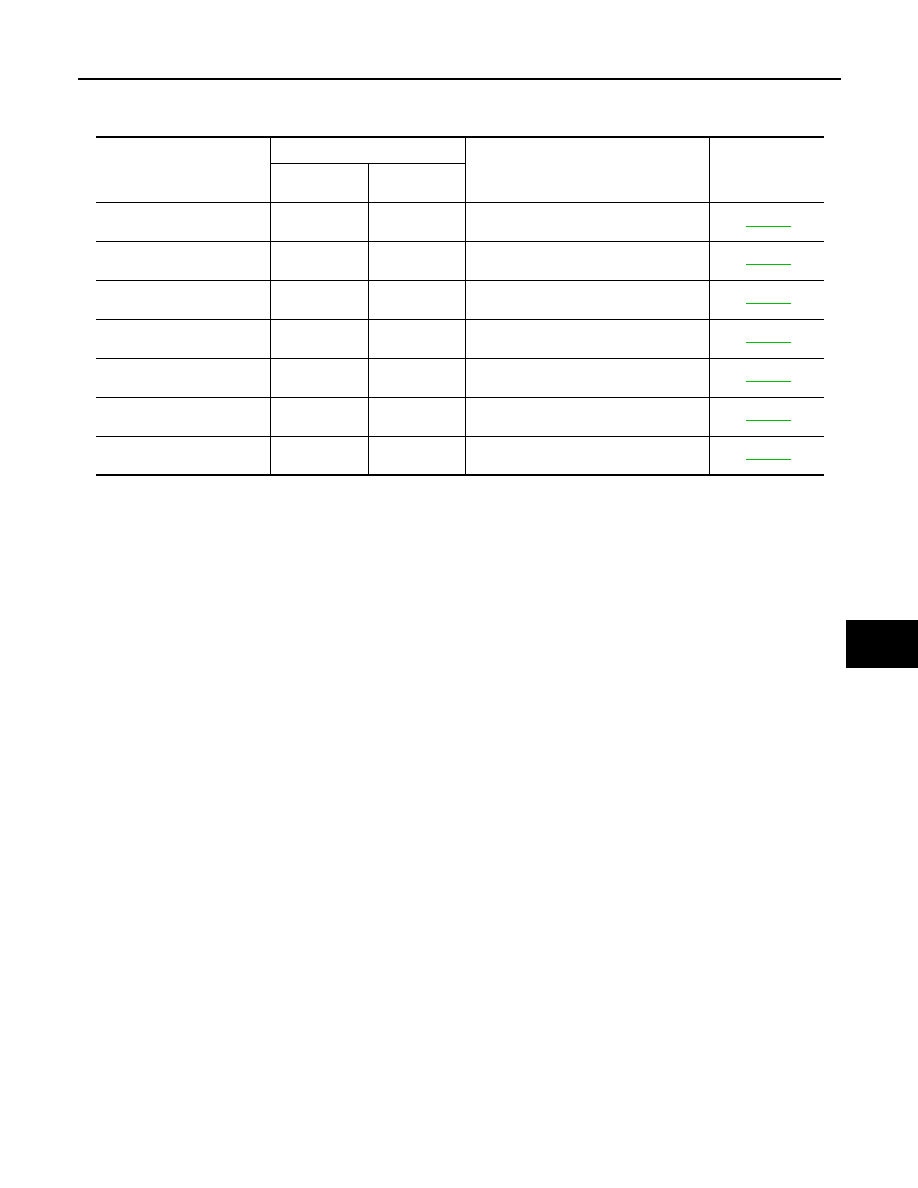
DTC Index
INFOID:0000000008463554
*:
• 0: Current malfunction is present.
• 1-39: Displayed if any previous malfunction is present when current condition is normal. The numeral value increases by one at each
IGN ON to OFF cycle from 1 to 39. The counter remains at 39 even if the number of cycles exceeds it. However, the counter is reset
to 1 if any malfunction is detected again, the normal operation is resumed and the ignition switch is turned from OFF to ON.
CONSULT display
Timing
*
Item
Reference page
Current mal-
function
Previous mal-
function
CAN COMM CIRCUIT
[U1000]
0
1-39
CAN communication
CONTROL UNIT (CAN)
[U1010]
0
1-39
Control unit
SEAT SLIDE
[B2112]
0
1-39
Seat slide motor output
SEAT RECLINING
[B2113]
0
1-39
Seat reclining motor output
STEERING TILT
[B2116]
0
1-39
Tilt motor output
UART COMM
[B2128]
0
1-39
UART communication
EEPROM
[B2130]
0
1-39
EEPROM
Revision: 2012 October
2013 Murano CrossCabriolet