Nissan Murano Z51 (2013 year). Manual - part 67


  Index      Manuals     Nissan Murano Z51 (2013 year) - Service and Repair Manual


Search            copyright infringement  


Content      ..     65      66      67      68     ..


Nissan Murano Z51 (2013 year). Manual - part 67


REAR LOWER LINK & COIL SPRING

RSU-9

< REMOVAL AND INSTALLATION >

C

D

F

G

H

I

J

K

L

M

A

B

RSU

N

O

P

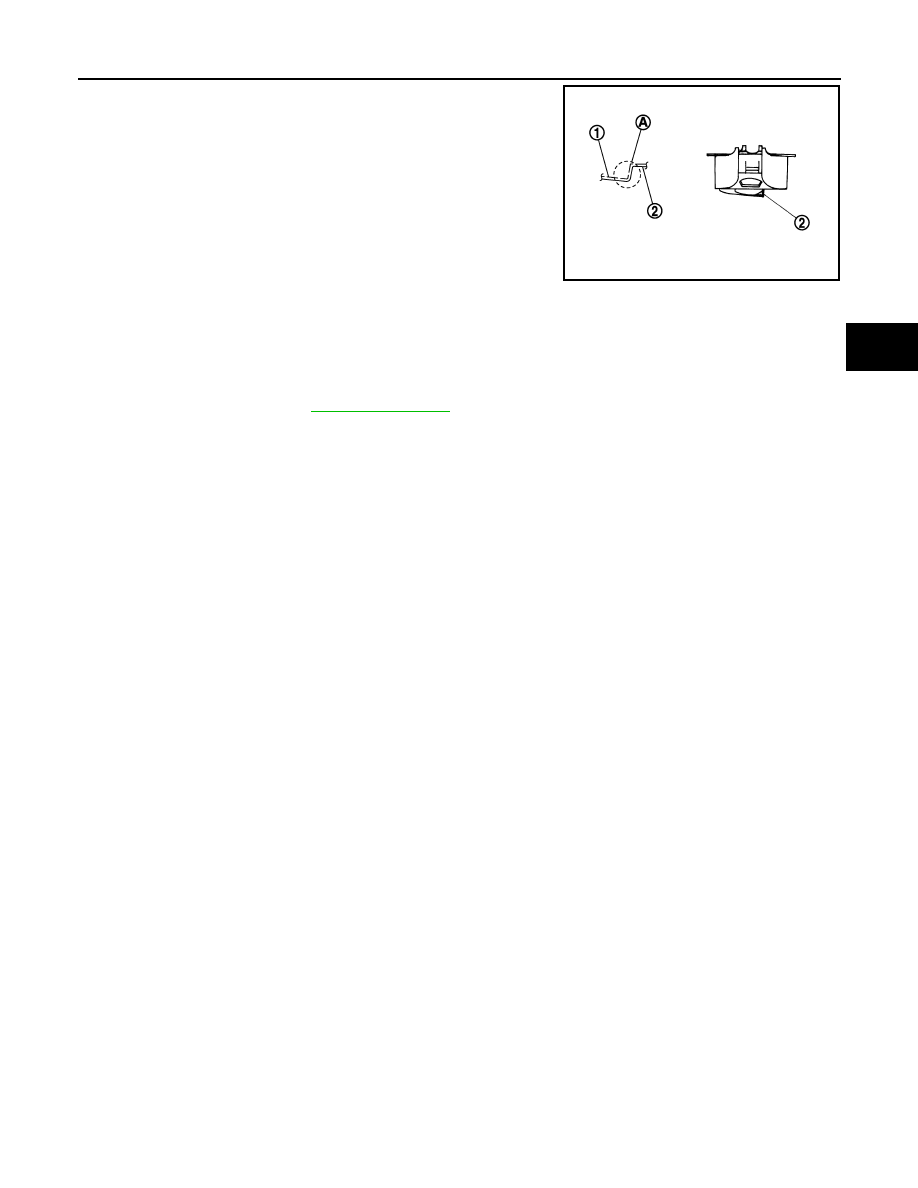
• Install coil spring by aligning lower end of the coil spring to step (A)

between rubber seat (1) and rear lower link (2).

CAUTION:

Set coil spring so that its paint marks are aligned with the
positions of 3.5 turns (2 places) and 4.5 turns (1 place) from
the bottom end of the coil spring.

• Perform the final tightening of rear suspension member and axle

installation position (rubber bushing) under unladen condition with
tires on level ground.

Inspection

INFOID:0000000008459238

INSPECTION AFTER REMOVAL

Check rear lower link, bushing and coil spring for deformation, crack, and damage. Replace it if necessary.

INSPECTION AFTER INSTALLATION

Check wheel alignment. Refer to 

RSU-6, "Inspection"

.

JPEIB0013ZZ

Revision: 2012 September

2013 MURANO

RSU-10

< REMOVAL AND INSTALLATION >

REAR SHOCK ABSORBER

REAR SHOCK ABSORBER

Exploded View

INFOID:0000000008459239

Removal and Installation

INFOID:0000000008459240

REMOVAL

1.

Remove tires with power tool.

2.

Separate stabilizer connecting rod (lower side). Refer to 

RSU-15, "Exploded View"

.

3.

Set suitable jack under axle housing to relieve the coil spring tension.

4.

Remove shock absorber mounting bolt (lower side) with power tool.

5.

Gradually lower the jack to remove it from front lower link.

6.

Remove shock absorber assembly mounting nuts (upper side)
(

), and remove shock absorber assembly.

INSTALLATION

Note the following, and install in the reverse order of removal.
• Perform final tightening of bolts and nuts at the shock absorber lower side (rubber bushing), under unladen

conditions with tires on level ground.

Disassembly and Assembly

INFOID:0000000008459241

DISASSEMBLY

CAUTION:

Never damage shock absorber piston rod when removing components from shock absorber. 

1.

Shock absorber

2.

Piston rod lock nut

3.

Shock absorber mounting bracket

4.

Bound bumper

Refer to 

GI-4, "Components"

 for symbols in the figure.

JPEIB0135GB

JPEIB0060ZZ

Revision: 2012 September

2013 MURANO

REAR SHOCK ABSORBER

RSU-11

< REMOVAL AND INSTALLATION >

C

D

F

G

H

I

J

K

L

M

A

B

RSU

N

O

P

1.

Wrap a shop cloth around lower side of shock absorber and fix it with a vise.

CAUTION:

Never set the cylindrical part of shock absorber with a vise.

2.

Secure the piston rod tip so that piston rod does not turn, and remove piston rod lock nut.

3.

Remove mounting bracket and bound bumper from shock absorber.

ASSEMBLY

Install in the reverse order of disassembly.

Inspection

INFOID:0000000008459242

INSPECTION AFTER REMOVAL

Check the following items, and replace the parts if necessary.
• Shock absorber assembly for deformation, cracks, damage.
• Welded and sealed areas for oil leakage.
• Piston rod for damage, uneven wear or distortion.
• Seal of shock absorber mounting bracket for cracks, damage and come off.

INSPECTION AFTER DISASSEMBLY

Bound Bumper

Check bound bumper for cracks and damage. Replace it if necessary.

Shock Absorber

Check the following items, and replace the part if necessary.
• Shock absorber for deformation, cracks, and other damage.
• Piston rod for damage, uneven wear, and distortion.

INSPECTION AFTER ASSEMBLY

Make sure piston rod on shock absorber is not damaged when attaching components to shock absorber.

INSPECTION AFTER INSTALLATION

Check wheel alignment. Refer to 

RSU-6, "Inspection"

.

Disposal

INFOID:0000000008459243

1.

Set shock absorber horizontally with the piston rod fully extended.

2.

Drill 2 – 3 mm (0.08 – 0.12 in) hole at the position (

) from top

as shown in the figure to release gas gradually.

CAUTION:

• Wear eye protection (safety glasses).
• Wear gloves.
• Be careful with metal chips or oil blown out by the com-

pressed gas.

NOTE:
• Drill vertically in this direction (

).

• Directly to the outer tube avoiding brackets.
• The gas is clear, colorless, odorless, and harmless.

3.

Position the drilled hole downward and drain oil by moving the piston rod several times.

CAUTION:

Dispose of drained oil according to the law and local regulations.

A

: 20 – 30 mm (0.79 – 1.18 in)

JPEIA0161ZZ

Revision: 2012 September

2013 MURANO

RSU-12

< REMOVAL AND INSTALLATION >

RADIUS ROD

RADIUS ROD

Exploded View

INFOID:0000000008459244

Removal and Installation

INFOID:0000000008459245

REMOVAL

1.

Remove tire with power tool.

2.

Remove wheel sensor and sensor harness. Refer to 

BRC-122, "REAR WHEEL SENSOR : Exploded

View"

.

3.

Remove rear lower link and coil spring. Refer to 

RSU-8, "Exploded View"

.

4.

Remove shock absorber mounting bolt (lower side) with power tool. Refer to 

RSU-10, "Exploded View"

.

5.

Remove front lower link mounting bolt and nut (axle housing side) with power tool. Refer to 

RSU-14,

"Exploded View"

.

6.

Loosen front lower link mounting bolt and nut (suspension member side). Refer to 

RSU-14, "Exploded

View"

.

7.

Remove radius rod mounting bolts and nuts (axle housing side) with power tool.

8.

Remove radius rod mounting bolt (rear suspension member side) with power tool, then remove radius
rod.

INSTALLATION

Note the following, and install in the reverse order of removal.
• Perform final tightening of rear suspension member and axle installation position (rubber bushing), under

unladen conditions with tires on level ground.

Inspection

INFOID:0000000008459246

INSPECTION AFTER REMOVAL

Check radius rod and bushing for any deformation, cracks, or damage. Replace if necessary.

INSPECTION AFTER INSTALLATION

1.

Check wheel sensor harness for proper connection. Refer to 

BRC-122, "REAR WHEEL SENSOR :

Exploded View"

.

1.

Upper seat

2.

Coil spring

3.

Rubber seat

4.

Rear lower link

5.

Rear suspension member

6.

Radius rod

7.

Front lower link

Refer to 

GI-4, "Components"

 for symbols in the figure.

JPEIB0146GB

Revision: 2012 September

2013 MURANO

RADIUS ROD

RSU-13

< REMOVAL AND INSTALLATION >

C

D

F

G

H

I

J

K

L

M

A

B

RSU

N

O

P

2.

Check wheel alignment. Refer to 

RSU-6, "Inspection"

.

Revision: 2012 September

2013 MURANO

RSU-14

< REMOVAL AND INSTALLATION >

FRONT LOWER LINK

FRONT LOWER LINK

Exploded View

INFOID:0000000008459247

Removal and Installation

INFOID:0000000008459248

REMOVAL

1.

Remove tire with power tool.

2.

Remove wheel sensor and sensor harness. Refer to 

BRC-122, "REAR WHEEL SENSOR : Exploded

View"

.

3.

Remove rear lower link and coil spring. Refer to 

RSU-8, "Exploded View"

.

4.

Remove shock absorber mounting bolt (lower side) with power tool. Refer to 

RSU-10, "Exploded View"

.

5.

Remove stabilizer bushing and stabilizer clamp. Refer to 

RSU-15, "Exploded View"

.

6.

Remove front lower link mounting bolts and nuts (rear suspension member side) with power tool.

7.

Remove front lower link mounting bolts and nuts (axle housing side) with power tool. 

8.

Remove front lower link.

INSTALLATION

Note the following, and install in the reverse order of removal.
• Perform final tightening of rear suspension member and axle installation position (rubber bushing), under

unladen conditions with tires on level ground.

Inspection

INFOID:0000000008459249

INSPECTION AFTER REMOVAL

Check front lower link and bushing for any deformation, cracks, or damage. Replace if necessary.

INSPECTION AFTER INSTALLATION

1.

Check wheel sensor harness for proper connection. Refer to 

BRC-122, "REAR WHEEL SENSOR :

Exploded View"

.

2.

Check wheel alignment. Refer to 

RSU-6, "Inspection"

.

1.

Upper seat

2.

Coil spring

3.

Rubber seat

4.

Rear lower link

5.

Rear suspension member

6.

Radius rod

7.

Front lower link

Refer to 

GI-4, "Components"

 for symbols in the figure.

JPEIB0146GB

Revision: 2012 September

2013 MURANO

REAR STABILIZER

RSU-15

< REMOVAL AND INSTALLATION >

C

D

F

G

H

I

J

K

L

M

A

B

RSU

N

O

P

REAR STABILIZER

Exploded View

INFOID:0000000008459250

Removal and Installation

INFOID:0000000008459251

REMOVAL

1.

Remove tires with power tool.

2.

Remove stabilizer connecting rod.

CAUTION:

Apply a matching mark to identify the installation position.

3.

Remove mounting bolts on stabilizer clamp and remove stabilizer bar with power tool.

INSTALLATION

Note the following, and install in the reverse order of removal.
• Check the matching mark when installing.
• Tighten the mounting nut to the specified torque while holding a hexagonal part of stabilizer connecting rod

side.

Inspection

INFOID:0000000008459252

INSPECTION AFTER REMOVAL

Check stabilizer bar, stabilizer bushing, stabilizer clamp, stabilizer connecting rod, for any deformation, crack
or damage. Replace if necessary.

1.

Suspension arm

2.

Stabilizer connecting rod

3.

Stabilizer bar

4.

Stabilizer bushing

5.

Stabilizer clamp

Refer to 

GI-4, "Components"

 for symbols in the figure.

JPEIB0268GB

Revision: 2012 September

2013 MURANO

RSU-16

< REMOVAL AND INSTALLATION >

REAR SUSPENSION ARM

REAR SUSPENSION ARM

Exploded View

INFOID:0000000008459253

NOTE:
Remove suspension arm with rear suspension member for AWD models. Refer to 

RSU-18, "Exploded View"

.

Removal and Installation

INFOID:0000000008459254

NOTE:
Remove suspension arm with rear suspension member for AWD models. Refer to 

RSU-18, "Exploded View"

.

REMOVAL

1.

Remove tire with power tool.

2.

Remove wheel sensor and sensor harness. Refer to 

BRC-122, "REAR WHEEL SENSOR : Exploded

View"

.

3.

Remove stabilizer connecting rod. Refer to 

RSU-15, "Exploded View"

.

4.

Remove cotter pin of suspension arm ball joint, and loosen nut.

5.

Use the ball joint remover to remove suspension arm from axle housing. Be careful not to damage ball
joint boot.

CAUTION:

Tighten temporarily mounting nut to prevent damage to threads and to prevent ball joint remover
from coming off.

6.

Remove suspension arm.

INSTALLATION

Note the following, and install in the reverse order of removal.
• Perform final tightening of rear suspension member installation position (rubber bushing), under unladen

conditions with tires on level ground.

Inspection

INFOID:0000000008459255

INSPECTION AFTER REMOVAL

Appearance

Check the following items, and replace the part if necessary.
• Suspension arm and bushing for deformation, cracks or damage.
• Boot of ball joint for cracks or damage, and also for grease leakage.

1.

Suspension arm

2.

Stopper rubber

3.

Rear suspension member

Refer to 

GI-4, "Components"

 for symbols in the figure.

JPEIB0141GB

Revision: 2012 September

2013 MURANO

REAR SUSPENSION ARM

RSU-17

< REMOVAL AND INSTALLATION >

C

D

F

G

H

I

J

K

L

M

A

B

RSU

N

O

P

Ball Joint Inspection

Manually move ball stud at least ten times by hand to check for smooth movement.

Swing Torque Inspection

1.

Before measurment, move ball stud at least ten times by hand to check for smooth movement.

2.

Hook spring balance (A) at cotter pin mounting hole. Confirm
spring balance measurement value is within specifications when
ball stud begins moving.

-

If swing torque exceeds the standard range, replace suspension
arm assembly.

Axial End Play Inspection

1.

Before measurment, move ball stud at least ten times by hand to check for smooth movement.

2.

Move tip of ball stud in axial direction to check for looseness.

-

If axial end play exceeds the standard range, replace suspension arm assembly.

INSPECTION AFTER INSTALLATION

1.

Check wheel sensor harness for proper connection. Refer to 

BRC-122, "REAR WHEEL SENSOR :

Exploded View"

.

2.

Check wheel alignment. Refer to 

RSU-6, "Inspection"

.

Swing torque

Refer to 

RSU-20, "Ball Joint"

.

JPEIA0005ZZ

Axial end play

Refer to 

RSU-20, "Ball Joint"

.

Revision: 2012 September

2013 MURANO

RSU-18

< UNIT REMOVAL AND INSTALLATION >

REAR SUSPENSION MEMBER

UNIT REMOVAL AND INSTALLATION

REAR SUSPENSION MEMBER

Exploded View

INFOID:0000000008459256

Removal and Installation

INFOID:0000000008459257

REMOVAL

1.

Remove tires with power tool.

2.

Remove caliper assembly. Hang caliper assembly in a place where it will not interfere with work. Refer to

BR-47, "BRAKE CALIPER ASSEMBLY : Exploded View"

.

CAUTION:

Avoid depressing brake pedal while caliper assembly is removed.

3.

Remove wheel sensor and sensor harness. Refer to 

BRC-122, "REAR WHEEL SENSOR : Exploded

View"

.

4.

Remove center muffler. Refer to 

EX-5, "Exploded View"

.

5.

Remove stabilizer bar. Refer to 

RSU-15, "Exploded View"

.

6.

Remove drive shaft (AWD models). Refer to 

RAX-15, "Exploded View"

.

7.

Remove propeller shaft (AWD models). Refer to 

DLN-78, "Exploded View"

.

8.

Remove harness from rear final drive and rear suspension member (AWD models).

9.

Remove rear final drive (AWD models). Refer to 

DLN-97, "Exploded View"

.

10. Separate the attachment between parking brake cable and vehicle and rear suspension member. Refer to

PB-6, "Exploded View"

.

11. Remove rear lower link and coil spring. Refer to 

RSU-8, "Exploded View"

12. Remove shock absorber (lower side). Refer to 

RSU-10, "Exploded View"

.

13. Set suitable jack under rear suspension member.

14. Remove member stay.

15. Remove rear suspension member and rebound stopper.
16. Slowly lower jack, then remove rear suspension member, suspension arm, radius rod, front lower link and

axle from vehicle as a unit.

17. Remove suspension arm. Refer to 

RSU-16, "Exploded View"

.

18. Remove radius rod. Refer to 

RSU-12, "Exploded View"

.

1.

Rebound stopper

2.

Rear suspension member

3.

Member stay

Refer to 

GI-4, "Components"

 for symbols in the figure.

JPEIB0148GB

Revision: 2012 September

2013 MURANO

REAR SUSPENSION MEMBER

RSU-19

< UNIT REMOVAL AND INSTALLATION >

C

D

F

G

H

I

J

K

L

M

A

B

RSU

N

O

P

19. Remove front lower link. Refer to 

RSU-14, "Exploded View"

.

INSTALLATION

Note the following, and install in the reverse order of the removal.
• Perform the final tightening of each of parts under unladen conditions, which were removed when removing

rear suspension assembly.

• Check wheel sensor harness for proper connection. Refer to 

BRC-122, "REAR WHEEL SENSOR :

Exploded View"

• Never reuse cotter pin.

Inspection

INFOID:0000000008459258

INSPECTION AFTER REMOVAL

Check rear suspension member for deformation, cracks, or any other damage. Replace if necessary.

INSPECTION AFTER INSTALLATION

1.

Check wheel sensor harness for proper connection. Refer to 

BRC-122, "REAR WHEEL SENSOR :

Exploded View"

.

2.

Adjust parking brake operation (stroke). 

PB-3, "Inspection and Adjustment"

.

3.

Check wheel alignment. Refer to 

RSU-6, "Inspection"

.

Revision: 2012 September

2013 MURANO

RSU-20

< SERVICE DATA AND SPECIFICATIONS (SDS) 

SERVICE DATA AND SPECIFICATIONS (SDS)

SERVICE DATA AND SPECIFICATIONS (SDS)

SERVICE DATA AND SPECIFICATIONS (SDS)

Wheel Alignment

INFOID:0000000008459259

FOR USA AND MEXICO MODELS

Measure value under unladen* conditions.

*: Fuel, engine coolant and lubricant are full. Spare tire, jack, hand tools and mats are in designated positions. 

FOR CANADA MODELS

Measure value under unladen* conditions.

*: Fuel, engine coolant and lubricant are full. Spare tire, jack, hand tools and mats are in designated positions. 

Ball Joint

INFOID:0000000008459260

Wheelarch Height

INFOID:0000000008459261

FOR USA MODELS

Item

Standard

Camber
Degree minute (Decimal degree)

Minimum

–1

°

 13

 (–1.21

°

)

Nominal

–0

°

 43

 (–0.72

°

)

Maximum

–0

°

 13

 (–0.21

°

)

Toe-in

Total toe-in
Distance

Minimum

In 0.9 mm (0.035 in)

Nominal

In 2.7 mm (0.106 in)

Maximum

In 4.5 mm (0.177 in)

Total toe-angle
Degree minute (Decimal degree)

Minimum

In 0

°

 04

 (In 0.07

°

)

Nominal

In 0

°

 12

 (In 0.20

°

)

Maximum

In 0

°

 20

 (In 0.33

°

)

Item

Standard

Camber
Degree minute (Decimal degree)

Minimum

–1

°

 11

 (–1.18

°

)

Nominal

–0

°

 41

 (–0.68

°

)

Maximum

–0

°

 11

 (–0.18

°

)

Toe-in

Total toe-in
Distance

Minimum

In 0.9 mm (0.035 in)

Nominal

In 2.7 mm (0.106 in)

Maximum

In 4.5 mm (0.177 in)

Total toe-angle
Degree minute (Decimal degree)

Minimum

In 0

°

 04

 (In 0.07

°

)

Nominal

In 0

°

 12

 (In 0.20

°

)

Maximum

In 0

°

 20

 (In 0.33

°

)

Item

Standard

Swing torque

0.5 – 3.4 N·m (0.06 – 0.34 kg-m, 5 – 30 in-lb)

Measurement on spring balance (cotter pinhole position)

8.1 – 54.8 N (0.83 – 5.6 kg, 1.82 – 12.32 lb)

Axial end play

0 mm (0 in)

Revision: 2012 September

2013 MURANO

SERVICE DATA AND SPECIFICATIONS (SDS)

RSU-21

< SERVICE DATA AND SPECIFICATIONS (SDS) 

C

D

F

G

H

I

J

K

L

M

A

B

RSU

N

O

P

Measure value under unladen* conditions.

*: Fuel, engine coolant and lubricant are full. Spare tire, jack, hand tools and mats are in designated positions.

FOR CANADA MODELS

Measure value under unladen* conditions.

*: Fuel, engine coolant and lubricant are full. Spare tire, jack, hand tools and mats are in designated positions.

FOR MEXICO MODELS

Item

Standard

Axle type

2WD

AWD

Wheel size

18 inch

20 inch

18 inch

20 inch

Grade

S

SL

LE

S

SL

LE

Front (Hr)

846 mm (33.31 in)

845 mm (33.27 in)

846 mm (33.31 in)

845 mm (33.27 in)

Rear (Hr)

859 mm (33.82 in)

858 mm (33.78 in)

858 mm (33.78 in)

857 mm (33.74 in)

SFA746B

Item

Standard

Wheel size

18 inch

20 inch

Grade

S

SL

LE

Front (Hr)

845 mm (33.27 in)

846 mm (33.31 in)

Rear (Hr)

858 mm (33.78 in)

857 mm (33.74 in)

SFA746B

Item

Standard

Axle type

2WD

AWD

Grade

S

SL

LE

Front (Hr)

846 mm (33.31 in)

845 mm (33.27 in)

Revision: 2012 September

2013 MURANO

RSU-22

< SERVICE DATA AND SPECIFICATIONS (SDS) 

SERVICE DATA AND SPECIFICATIONS (SDS)

Measure value under unladen* conditions.

*: Fuel, engine coolant and lubricant are full. Spare tire, jack, hand tools and mats are in designated positions.

Rear (Hr)

859 mm (33.82 in)

858 mm (33.78 in)

857 mm (33.74 in)

Item

Standard

Axle type

2WD

AWD

Grade

S

SL

LE

SFA746B

Revision: 2012 September

2013 MURANO

SB-1

RESTRAINTS

C

D

E

F

G

I

J

K

L

M

SECTION 

SB

A

B

SB

N

O

P

CONTENTS

SEAT BELT

PRECAUTION ...............................................

2

PRECAUTIONS ...................................................

2

FOR USA AND CANADA ............................................

2

FOR USA AND CANADA : Precaution for Supple-
mental Restraint System (SRS) "AIR BAG" and 
"SEAT BELT PRE-TENSIONER" ............................
..

2

FOR USA AND CANADA : Precaution for Seat 
Belt Service  .............................................................
..

2

FOR MEXICO  ..............................................................

3

FOR MEXICO : Precaution for Supplemental Re-
straint System (SRS) "AIR BAG" and "SEAT BELT 
PRE-TENSIONER" .................................................
..

3

FOR MEXICO : Precaution for Seat Belt Service ......

3

REMOVAL AND INSTALLATION ................

5

FRONT SEAT BELT ............................................

5

SEAT BELT RETRACTOR ..........................................

5

SEAT BELT RETRACTOR : Inspection  ....................

5

SEAT BELT RETRACTOR : Exploded View  ............

7

SEAT BELT RETRACTOR : Removal and Instal-
lation ........................................................................
.

7

SEAT BELT BUCKLE .................................................

8

SEAT BELT BUCKLE : Inspection  ...........................

8

SEAT BELT BUCKLE : Exploded View  ....................

9

SEAT BELT BUCKLE : Removal and Installation .....

9

REAR SEAT BELT ............................................

10

SEAT BELT RETRACTOR  ........................................

10

SEAT BELT RETRACTOR : Inspection  ..................

10

SEAT BELT RETRACTOR : Exploded View  ...........

12

SEAT BELT RETRACTOR : Removal and Instal-
lation ........................................................................

13

SEAT BELT BUCKLE ................................................

13

SEAT BELT BUCKLE : Inspection  ..........................

13

SEAT BELT BUCKLE : Exploded View  ...................

14

SEAT BELT BUCKLE : Removal and Installation ....

14

Revision: 2012 September

2013 MURANO

SB-2

< PRECAUTION >

PRECAUTIONS

PRECAUTION

PRECAUTIONS

FOR USA AND CANADA

FOR USA AND CANADA : Precaution for Supplemental Restraint System (SRS) "AIR 
BAG" and "SEAT BELT PRE-TENSIONER"

INFOID:0000000008455305

The Supplemental Restraint System such as “AIR BAG” and “SEAT BELT PRE-TENSIONER”, used along
with a front seat belt, helps to reduce the risk or severity of injury to the driver and front passenger for certain
types of collision. This system includes seat belt switch inputs and dual stage front air bag modules. The SRS
system uses the seat belt switches to determine the front air bag deployment, and may only deploy one front
air bag, depending on the severity of a collision and whether the front occupants are belted or unbelted.
Information necessary to service the system safely is included in the “SRS AIR BAG” and “SEAT BELT” of this
Service Manual.

WARNING:

Always observe the following items for preventing accidental activation.
• To avoid rendering the SRS inoperative, which could increase the risk of personal injury or death in

the event of a collision that would result in air bag inflation, all maintenance must be performed by
an authorized NISSAN/INFINITI dealer.

• Improper maintenance, including incorrect removal and installation of the SRS, can lead to personal

injury caused by unintentional activation of the system. For removal of Spiral Cable and Air Bag
Module, see “SRS AIR BAG”.

• Never use electrical test equipment on any circuit related to the SRS unless instructed to in this Ser-

vice Manual. SRS wiring harnesses can be identified by yellow and/or orange harnesses or harness
connectors.

PRECAUTIONS WHEN USING POWER TOOLS (AIR OR ELECTRIC) AND HAMMERS

WARNING:

Always observe the following items for preventing accidental activation.
• When working near the Air Bag Diagnosis Sensor Unit or other Air Bag System sensors with the

ignition ON or engine running, never use air or electric power tools or strike near the sensor(s) with
a hammer. Heavy vibration could activate the sensor(s) and deploy the air bag(s), possibly causing
serious injury.

• When using air or electric power tools or hammers, always switch the ignition OFF, disconnect the

battery, and wait at least 3 minutes before performing any service.

FOR USA AND CANADA : Precaution for Seat Belt Service

INFOID:0000000008455306

CAUTION:

• Before removing the front seat belt pre-tensioner assembly, turn the ignition switch off, disconnect

both battery cables and wait at least 3 minutes.

• Never use electrical test equipment for front seat belt pre-tensioner connector.
• After replacing or reinstalling front seat belt pre-tensioner assembly, or reconnecting front seat belt

pre-tensioner connector, check the system function. Refer to 

SRC-15, "Description"

.

• Never use disassembled buckle or seat belt assembly.
• Replace anchor bolts if they are deformed or worn out.
• Never oil tongue and buckle.
• If any component of seat belt assembly is questionable, never repair. Replace the entire seat belt

assembly.

• If webbing is cut, frayed or damaged, replace seat belt assembly.
• When replacing seat belt assembly, use a genuine NISSAN seat belt assembly.

AFTER A COLLISION

WARNING:

Inspect all seat belt assemblies including retractors and attached hardware after any collision.
NISSAN/INFINITI recommends that all seat belt assemblies in use during a collision be replaced
unless the collision was minor and the belts show no damage and continue to operate properly. Fail-
ure to do so could result in serious personal injury in an accident. Seat belt assemblies not in use dur-
ing a collision should also be replaced if either damage or improper operation is noted. Seat belt pre-

Revision: 2012 September

2013 MURANO


Content      ..     65      66      67      68     ..