Nissan Murano Z51 (2013 year). Manual - part 23
DEF-18
< DTC/CIRCUIT DIAGNOSIS >
DOOR MIRROR DEFOGGER
DOOR MIRROR DEFOGGER
Description
INFOID:0000000008456564
Power is supplied to the door mirror defogger with BCM control.
Component Function Check
INFOID:0000000008456565
1.
CHECK DOOR MIRROR DEFOGGER
1.
Perform Active Test (“REAR DEFOGGER”) with CONSULT.
2.
Touch “ON”.
3.
Check that both side door mirror glass is getting warmer.
Is the inspection result normal?
YES
>> Door mirror defogger is OK.
NO
>> Refer to
.
Diagnosis Procedure
INFOID:0000000008456566
1.
CHECK FUSE
1.
Turn ignition switch OFF.
2.
Check 10A fuse (No.13, located in fuse block (J/B).
-
Is the inspection result normal?
YES
>> GO TO 2.
NO
>> Replace the blown fuse after repairing the affected circuit if a fuse is blown.
2.
CHECK FUSE BLOCK (J/B)
1.
Turn ignition switch ON.
2.
Check voltage between fuse block (J/B) connector (fuse block side) and ground.
Is the inspection result normal?
YES
>> GO TO 3.
NO
>> Replace fuse block (J/B).
3.
CHECK DOOR MIRROR DEFOGGER CIRCUIT
Check voltage between door mirror defogger (driver side) connector and ground.
Is the inspection result normal?
YES
>> GO TO 4.
NO
>> Repair or replace the harness or connector.
4.
CHECK INTERMITTENT INCIDENT
Check intermittent incident. Refer to
GI-45, "Intermittent Incident"
Is the inspection result normal?
>> INSPECTION END
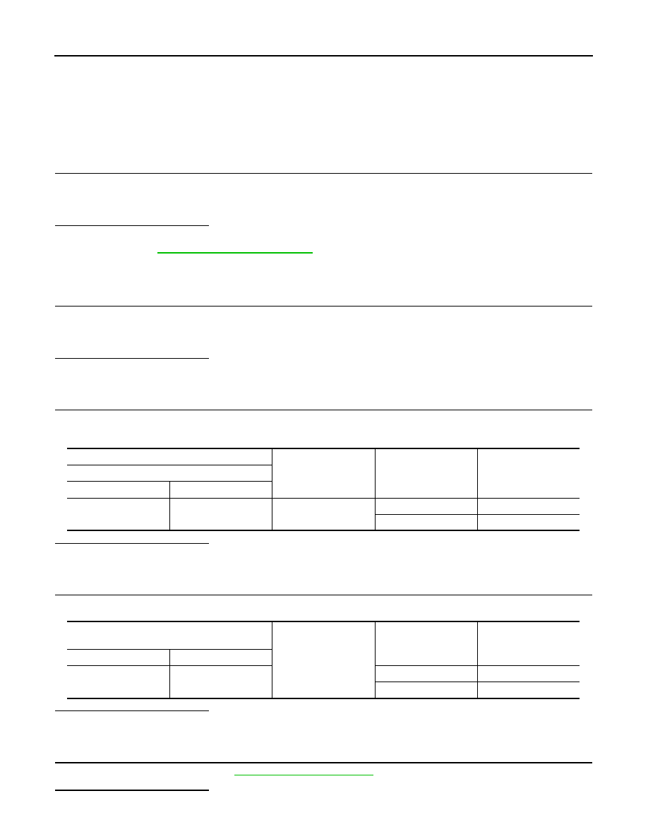
(+)
(-)
Condition of rear win-
dow defogger switch
Voltage (V)
(Approx.)
Fuse block (J/B)
Connector
Terminal
M3
10C
Ground
ON
Battery voltage
OFF
0
Door mirror defogger
(driver side)
Ground
Condition of rear win-
dow defogger switch
Voltage (V)
(Approx.)
Connector
Terminal
D3
7
ON
Battery voltage
OFF
0
Revision: 2012 September
2013 MURANO