Nissan Murano Z51 (2013 year). Manual - part 21


  Index      Manuals     Nissan Murano Z51 (2013 year) - Service and Repair Manual


Search            copyright infringement  


Content      ..     19      20      21      22     ..


Nissan Murano Z51 (2013 year). Manual - part 21


RADIATOR

CO-17

< REMOVAL AND INSTALLATION >

C

D

E

F

G

H

I

J

K

L

M

A

CO

N

P

O

Removal and Installation

INFOID:0000000008457848

REMOVAL

WARNING:

Never remove radiator cap when engine is hot. Serious burns could occur from high-pressure engine
coolant escaping from radiator. Wrap a thick cloth around the cap. Slowly turn it a quarter of a turn to
release built-up pressure. Carefully remove radiator cap by turning it all the way.
NOTE:
When removing components such as hoses, tubes/lines, etc., cap or plug openings to prevent fluid from spill-
ing.
1.

Remove the following parts:
• Engine under cover.
• Radiator core support covers (RH and LH): Refer to 

EM-30, "Exploded View"

.

• Air duct (inlet): Refer to 

EM-30, "Exploded View"

.

• Front grille: Refer to 

EXT-18, "Exploded View"

.

• Horn: Refer to 

HRN-5, "Exploded View"

.

• Hood lock: Refer to 

DLK-293, "Exploded View"

.

2.

Drain engine coolant from radiator. Refer to 

CO-11, "Draining"

.

CAUTION:

• Perform this step when the engine is cold.
• Never spill engine coolant on drive belt.

3.

Disconnect reservoir tank hose from radiator pipe (upper).

4.

Disconnect CVT fluid cooler hoses from radiator.
• Install blind plug to avoid leakage of CVT fluid.

5.

Remove radiator cap adapter and each radiator hoses (upper) and radiator pipe (upper) assembly.

CAUTION:

Be careful not to allow engine coolant to contact drive belt.

6.

Disconnect radiator hose (lower) from radiator.

7.

Remove condenser. Refer to 

HA-49, "Exploded View"

.

CAUTION:

Be careful not to damage condenser core.
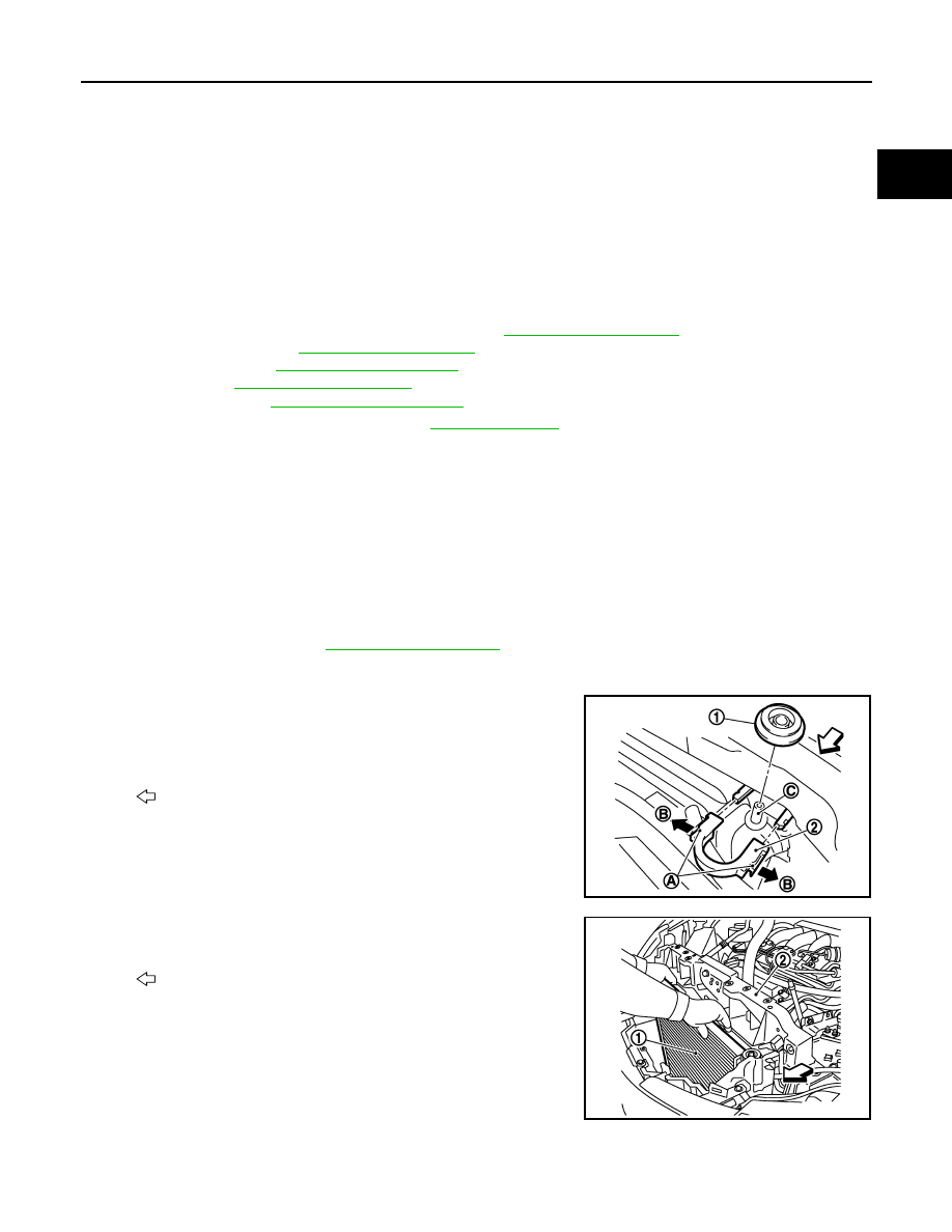
8.

Remove each radiator upper clips (2) by pulling the tabs (A) out-
side to release the lock (B) and then remove each mounting rub-
bers (upper) (1).

CAUTION:

Never pull the tabs outside excessively to prevent it from
damping.

9.

Lift up and remove radiator (1) from front of radiator core support
(2).

CAUTION:

Be careful not to damage or scratch on radiator core.

INSTALLATION

CAUTION:

Do not reuse O-rings.

C

: Mounting pin

: Vehicle front

JPBIA1689ZZ

: Vehicle front

JPBIA1699ZZ

Revision: 2012 September

2013 MURANO

CO-18

< REMOVAL AND INSTALLATION >

RADIATOR

Note the following, and install in the reverse order of removal.

Radiator Upper Clip

Install each radiator upper clips on radiator core connection as follows:
1.

Install each mounting rubbers (upper) (1) on mounting pins (A)
of radiator.

2.

Align each radiator upper clips (2) with radiator core connection
(B), then insert each radiator upper clips straight into radiator
core connections until a click is heard.

3.

After connecting each radiator upper clips, use the following
method to check it is fully connected.
• Visually confirm that each radiator upper clips are connected

to radiator core connections.

• Move each radiator upper clips and the radiator forward and backward to check they are securely con-

nected.

Radiator hose

CAUTION:

• Use genuine mounting bolts for the cooling fan assembly and strictly observe the tightening torque.

(Breakage prevention for radiator)

NOTE:
• Insert the radiator hose (1) all the way to the stopper (2) or by 33 mm (1.30 in) (hose without a stopper).

• For the orientation of the hose clamp pawl, refer to the figure.

*Refer to the illustrations for the specific position each hose clamp tab.

: Vehicle front

JPBIA1690ZZ

Unit mm (in)

A.

Radiator side

B.

Engine side

JPBIA4294GB

Radiator hose

Hose end

Paint mark

Position of hose clamp*

Radiator hose (upper)

Radiator side

Right side

C

Radiator pipe radiator side

No marking

B

Radiator pipe engine side

No marking

C

Engine side

Upper 

D

Radiator hose (lower)

Radiator side

Upper

A

Radiator pipe radiator side

No marking

A

Radiator pipe engine side

No marking

A

Engine side

Upper

E

Revision: 2012 September

2013 MURANO

RADIATOR

CO-19

< REMOVAL AND INSTALLATION >

C

D

E

F

G

H

I

J

K

L

M

A

CO

N

P

O

• The angle (b) created by the hose clamp pawl and the specified

line (A) must be within 

±

15

°

 as shown in the figure.

• To install hose clamps (1), check that the dimension (A) from the

end of the paint mark (2) on the radiator hose to the hose clamp is
within the reference value. 

Inspection

INFOID:0000000008457849

INSPECTION AFTER INSTALLATION

• Check for leakage of engine coolant using the radiator cap tester adapter (commercial service tool) and the

radiator cap tester (commercial service tool). Refer to 

CO-11, "Inspection"

.

• Start and warm up the engine. Visually check that there is no leakage of engine coolant and CVT fluid.

F.

View F

g.

45

°

Vehicle upper

Vehicle rear

JPBIA4777ZZ

JPBIA4295ZZ

Dimension “A”

(

1) – (+1) mm

(

0.04) – (+0.04) in

JSBIA0241ZZ

Revision: 2012 September

2013 MURANO

CO-20

< REMOVAL AND INSTALLATION >

COOLING FAN

COOLING FAN

Exploded View

INFOID:0000000008457850

Removal and Installation

INFOID:0000000008457851

REMOVAL

1.

Remove the following parts.
• Engine under cover
• Air duct (inlet): Refer to 

EM-30, "Exploded View"

.

• Oil level gauge: Refer to 

EM-110, "Exploded View"

.

• Battery and battery tray: Refer to 

PG-118, "Removal and Installation"

.

2.

Drain engine coolant from radiator. Refer to 

CO-11, "Draining"

.

CAUTION:

• Perform this step engine is cold.
• Never spill engine coolant on drive belt.

3.

Remove radiator cap adapter and each radiator hoses (upper) and radiator pipe (upper) assembly. Refer
to 

CO-16, "Exploded View"

.

4.

Disconnect harness connector from fan motors (RH and LH), and move harness to aside.

5.

Disconnect harness connector from crash zone sensor, and move harness to aside. Refer to 

SR-21,

"Exploded View"

.

6.

Remove battery tray bracket mounting bolts, and move battery tray bracket to aside.

1.

Fan motor (LH)

2.

Fan motor (RH)

3.

Fan shroud

4.

Mounting rubber

5.

Cooling fan (RH)

6.

Cooling fan (LH)

A.

Apply on fan motor shaft

: Vehicle front


: Apply genuine high strength thread locking sealant or equivalent.

: N·m (kg-m, in-lb)

JPBIA1687GB

Revision: 2012 September

2013 MURANO

COOLING FAN

CO-21

< REMOVAL AND INSTALLATION >

C

D

E

F

G

H

I

J

K

L

M

A

CO

N

P

O

7.

Remove cooling fan assembly.

CAUTION:

Be careful not to damage or scratch on radiator core.

INSTALLATION

Note the following, and install in the reverse order of removal.

CAUTION:

Only use genuine parts for cooling fan mounting bolt and observe the specified torque (to prevent
radiator from being damaged).
NOTE:
Cooling fans are controlled by ECM. For details, refer to 

EC-73, "System Diagram"

.

Disassembly and Assembly

INFOID:0000000008457852

DISASSEMBLY

1.

Remove cooling fan mounting nuts, and then remove the cooling fans (RH and LH).

2.

Remove fan motors (RH and LH).

ASSEMBLY

Note the following, and assemble in the reverse order of disassembly.

CAUTION:

RH and LH cooling fans are different. Be careful not to misassemble them.
• Install each fan in the following position.

• Secure the harness tightly to the fan shroud to prevent the fan rotation area from being loose.

Inspection

INFOID:0000000008457853

INSPECTION AFTER DISASSEMBLY

Cooling Fan

Inspect cooling fan for crack or unusual bend.
• If anything is found, replace cooling fan.

Right side

: 11 blades

Left side

: 9 blades

Revision: 2012 September

2013 MURANO

CO-22

< REMOVAL AND INSTALLATION >

WATER PUMP

WATER PUMP

Exploded View

INFOID:0000000008457854

Removal and Installation

INFOID:0000000008457855

CAUTION:

• When removing water pump assembly, be careful not to get engine coolant on drive belt.
• Water pump cannot be disassembled and should be replaced as a unit.
• After installing water pump, connect hose and clamp securely, then check for leakage using the radi-

ator cap tester (commercial service tool) and the radiator cap tester adapter (commercial service
tool).

REMOVAL

1.

Remove the following parts.
• Air duct (inlet): Refer to 

EM-30, "Exploded View"

.

• Engine cover: Refer to 

EM-28, "Exploded View"

.

• Engine under cover
• Front road wheel and tire
• Splash guard (RH): Refer to 

EXT-23, "FENDER PROTECTOR : Exploded View"

.

2.

Drain engine coolant from radiator. Refer to 

CO-11, "Draining"

.

CAUTION:

• Perform this step when the engine is cold.
• Never spill engine coolant on drive belt.

3.

Remove drive belt. Refer to 

EM-16, "Removal and Installation"

.

4.

Remove idler pulleys. Refer to 

EM-29, "Exploded View"

.

1.

Timing chain tensioner (primary)

2.

Valve timing control cover gasket 
(bank 1)

3.

Valve timing control cover (bank 1)

4.

Water drain plug (front)

5.

Water pump cover

6.

O-ring

7.

O-ring

8.

Water pump

A.

Apply engine coolant

B.

Identify with white mark

: Always replace after every disassembly.

: N·m (kg-m, ft-lb)

: N·m (kg-m, in-lb)

: Should be lubricated with oil.

: Sealing point

JPBIA2460GB

Revision: 2012 September

2013 MURANO

WATER PUMP

CO-23

< REMOVAL AND INSTALLATION >

C

D

E

F

G

H

I

J

K

L

M

A

CO

N

P

O

5.

Remove reservoir tank of radiator. Refer to 

CO-16, "Exploded View"

.

6.

Remove reservoir tank of power steering oil pump with piping connected, and move it to aside. Refer to

ST-62, "Exploded View"

.

7.

Support oil pan (lower) bottom with transmission jack.

8.

Remove engine mounting insulator (RH), engine mounting bracket (RH) and upper torque rod. Refer to

EM-71, "2WD : Exploded View"

 (2WD models) or 

EM-80, "AWD : Exploded View"

 (AWD models).

9.

Remove water drain plug (front) on water pump side of cylinder block to drain engine coolant from engine
inside.

10. Remove valve timing control cover (bank 1) and water pump cover from front timing chain case.

• Use the seal cutter [SST: KV10111100 (J-37228)] to cut liquid gasket for removal.

11. Remove timing chain tensioner (primary) as follows:

a.

Remove lower mounting bolt (1).

CAUTION:

Be careful not to drop mounting bolt inside timing chain
case.

b.

Loosen upper mounting bolt (2) slowly, and then turn chain ten-
sioner (primary) (3) on the mounting bolt so that plunger (4) is
fully expanded.
NOTE:
Even if plunger is fully expanded, it is not dropped from the body
of timing chain tensioner (primary).

c.

Turn crankshaft pulley clockwise so that timing chain on the tim-
ing chain tensioner (primary) side is loose.

d.

Remove upper mounting bolt, and then remove timing chain ten-
sioner (primary).

CAUTION:

Be careful not to drop mounting bolt inside timing chain
case.

12. Remove water pump as follows:

JPBIA0085ZZ

PBIC4820E

PBIC3576E

Revision: 2012 September

2013 MURANO

CO-24

< REMOVAL AND INSTALLATION >

WATER PUMP

a.

Remove three water pump mounting bolts. Secure a gap
between water pump gear and timing chain, by turning crank-
shaft pulley counterclockwise until timing chain looseness on
water pump sprocket becomes maximum. 

b.

Screw M8 bolts [pitch: 1.25 mm (0.0492 in) length: approxi-
mately 50 mm (1.97 in)] into water pumps upper and lower
mounting bolt holes until they reach timing chain case. Then,
alternately tighten each bolt for a half turn, and pull out water
pump.

CAUTION:

• Pull straight out while preventing vane from contacting

socket in installation area.

• Remove water pump without causing sprocket to contact

timing chain.

c.

Remove M8 bolts and O-rings from water pump.

CAUTION:

Never disassemble water pump.

INSTALLATION

CAUTION:

Do not reuse O-rings.

1.

Install new O-rings to water pump.

CAUTION:

Do not reuse O-rings.
• Apply engine oil and engine coolant to O-rings as shown in the

figure.

• Locate O-ring with white paint mark to engine front side.

2.

Install water pump.

CAUTION:

Never allow cylinder block to nip O-rings when installing
water pump.
• Check that timing chain and water pump sprocket are

engaged.

• Insert water pump by tightening mounting bolts alternately and

evenly.

3.

Install timing chain tensioner (primary) as follows:

PBIC1193E

JLC357B

PBIC1397E

SLC031B

Revision: 2012 September

2013 MURANO

WATER PUMP

CO-25

< REMOVAL AND INSTALLATION >

C

D

E

F

G

H

I

J

K

L

M

A

CO

N

P

O

a.

Turn crankshaft pulley clockwise so that timing chain on the tim-
ing chain tensioner (primary) side is loose.

b.

Pull plunger stopper tab (A) up (or turn lever downward) so as to
remove plunger stopper tab from the ratchet of plunger (D).
NOTE:
Plunger stopper tab and lever (C) are synchronized.

c.

Push plunger into the inside of tensioner body.

d.

Hold plunger in the fully compressed position by engaging
plunger stopper tab with the tip of ratchet.

e.

To secure lever, insert stopper pin (E) through hole of lever into
tensioner body hole (B).
• The lever parts and the tab are synchronized. Therefore, the

plunger will be secured under this condition.

NOTE:
Figure shows the example of 1.2 mm (0.047 in) diameter thin screwdriver being used as the stopper pin.

f.

Install timing chain tensioner (primary).
• Remove dust and foreign material completely from backside of timing chain tensioner (primary) and

from installation area of rear timing chain case.

g.

Remove stopper pin (A).

h.

Check again that timing chain and water pump sprocket are engaged.

4.

Install valve timing control cover (bank 1) and water pump cover as follows:

a.

Before installing, remove all traces of old liquid gasket from mating surface of water pump cover using
scraper. Also remove traces of old liquid gasket from the mating surface of front timing chain case.

b.

Apply a continuous bead of liquid gasket with the tube presser
(commercial service tool) to mating surface of water pump cover
(1).

Use Genuine RTV Silicone Sealant or equivalent. Refer to

GI-22, "Recommended Chemical Products and Sealants"

.

CAUTION:

Attaching should be done within 5 minutes after coating.

c.

Tighten mounting bolts.

PBIC4820E

JPBIA0118ZZ

JPBIA1774ZZ

a

φ

2.3 - 3.3 mm (0.091 - 0.130 in)

JPBIA1722ZZ

Revision: 2012 September

2013 MURANO

CO-26

< REMOVAL AND INSTALLATION >

WATER PUMP

5.

Install water drain plug (front) on water pump side of cylinder block.
• Apply liquid gasket to the thread of water drain plug (front).

Use Genuine RTV Silicone Sealant or equivalent. Refer to 

GI-22, "Recommended Chemical Prod-

ucts and Sealants"

.

6.

Install in the reverse order of removal after this step.
• After starting engine, let idle for three minutes, then rev engine up to 3,000 rpm under no load to

purge air from the high-pressure chamber of chain tensioner. Engine may produce a rattling
noise. This indicates that air still remains in the chamber and is not a matter of concern.

Inspection

INFOID:0000000008457856

INSPECTION AFTER REMOVAL

• Check for badly rusted or corroded water pump body assembly.
• Check for rough operation due to excessive end play.
• If anything is found, replace water pump.

INSPECTION AFTER INSTALLATION

• Check for leakage of engine coolant using the radiator cap tester adapter (commercial service tool) and the

radiator cap tester (commercial service tool). Refer to 

CO-11, "Inspection"

.

• Start and warm up the engine. Visually check that there is no leakage of engine coolant.

SLC943A

Revision: 2012 September

2013 MURANO

WATER INLET AND THERMOSTAT ASSEMBLY

CO-27

< REMOVAL AND INSTALLATION >

C

D

E

F

G

H

I

J

K

L

M

A

CO

N

P

O

WATER INLET AND THERMOSTAT ASSEMBLY

Exploded View

INFOID:0000000008457857

Removal and Installation

INFOID:0000000008457858

REMOVAL

1.

Drain engine coolant from radiator drain plug at the bottom of radiator, and from water drain plug at the
front of cylinder block. Refer to 

CO-11, "Draining"

 and 

EM-89, "Setting"

.

CAUTION:

• Perform this step when the engine is cold.
• Never spill engine coolant on drive belt.

2.

Remove reservoir tank of radiator, and move it aside. Refer to 

CO-16, "Exploded View"

.

3.

Remove intake valve timing control solenoid valve (bank 2). Refer to

EM-56, "Exploded View"

.

4.

Disconnect radiator hose (lower) from water inlet and thermostat assembly.

5.

Remove water inlet and thermostat assembly (1).

CAUTION:

Never disassemble water inlet and thermostat assembly.
Replace them as a unit, if necessary.

INSTALLATION

Note the following, and install in the reverse order of removal.
• Be careful not to spill engine coolant over engine room. Use rag to absorb engine coolant.

1.

Gasket

2.

Water inlet and thermostat assembly

3.

Clamp

4.

Radiator hose (lower)

A.

To radiator

: Always replace after every disassembly.

: N·m (kg-m, in-lb)

JPBIA1688GB

A

: Never loosen these screw

JPBIA0261ZZ

Revision: 2012 September

2013 MURANO

CO-28

< REMOVAL AND INSTALLATION >

WATER INLET AND THERMOSTAT ASSEMBLY

Inspection

INFOID:0000000008457859

INSPECTION AFTER REMOVAL

1.

Check valve seating condition at ordinary room temperatures. It should seat tightly.

2.

Check valve operation.

• If the malfunctioning condition, when valve seating at ordinary

room temperature, or measured values are out of the standard,
replace water inlet and thermostat assembly.

INSPECTION AFTER INSTALLATION

• Check for leakage of engine coolant using the radiator cap tester adapter (commercial service tool) and the

radiator cap tester (commercial service tool). Refer to 

CO-11, "Inspection"

.

• Start and warm up the engine. Visually check that there is no leakage of engine coolant.

Thermostat (Standard)

: Refer to 

CO-31, "Thermostat"

.

SLC949A

Revision: 2012 September

2013 MURANO

WATER OUTLET AND WATER PIPING

CO-29

< REMOVAL AND INSTALLATION >

C

D

E

F

G

H

I

J

K

L

M

A

CO

N

P

O

WATER OUTLET AND WATER PIPING

Exploded View

INFOID:0000000008457860

Removal and Installation

INFOID:0000000008457861

REMOVAL

1.

Remove air duct (inlet), radiator core support covers (RH and LH), air cleaner cases (upper and lower)
with mass air flow sensor and air duct assembly. Refer to 

EM-30, "Exploded View"

.

2.

Remove engine cover. Refer to 

EM-28, "Exploded View"

.

3.

Drain engine coolant from radiator drain plug at the bottom of radiator, and from water drain plug at the
front of cylinder block. Refer to 

CO-11, "Draining"

 and 

EM-89, "Setting"

.

CAUTION:

1.

Heater hose

2.

Clamp

3.

Water hose

4.

Clamp

5.

Water outlet

6.

Gasket

7.

Gasket

8.

Water connector

9.

O-ring

10. Water bypass pipe

11.

Clamp

12.

Water hose

13. Heater pipe

14.

Water hose

15.

Heater hose

16. Engine coolant temperature sensor

17.

Clamp

18.

Radiator hose (upper)

A.

To heater core

B.

To electric throttle control actuator

C.

To oil cooler

D.

To radiator

: Always replace after every disassembly.

: N·m (kg-m, ft-lb)

: N·m (kg-m, in-lb)

JPBIA1691GB

Revision: 2012 September

2013 MURANO

CO-30

< REMOVAL AND INSTALLATION >

WATER OUTLET AND WATER PIPING

• Perform this step when the engine is cold.
• Never spill engine coolant on drive belt.

4.

Remove battery and battery tray. Refer to 

PG-118, "Removal and Installation"

.

5.

Remove CVT fluid charging pipe and CVT fluid level gauge. Refer to 

TM-169, "Exploded View"

.

6.

Move CVT control cable aside. Refer to 

TM-160, "Exploded View"

.

7.

Remove vacuum tube (front) mounting bolt from water outlet. Refer to 

EM-71, "2WD : Exploded View"

(2WD models) or 

EM-80, "AWD : Exploded View"

 (AWD models).

8.

Remove radiator hose (upper) from water outlet.

9.

Remove water hoses and heater hoses.

10. Disconnect harness connectors, and move harness to aside.

11. Remove engine coolant temperature sensor if necessary.

CAUTION:

Be careful not to damage engine coolant temperature sensor.

12. Remove water outlet, heater pipe, water bypass pipe and water connector.

INSTALLATION

CAUTION:

Do not reuse O-rings.
Note the following, and install in the reverse order of removal.
• Securely insert each hose, and install clamp at a position where it does not interfere with the pipe bulge.
• When inserting water bypass pipe and heater pipe into water connector, apply neutral detergent to O-ring.

Inspection

INFOID:0000000008457862

INSPECTION AFTER INSTALLATION

• Check for leakage of engine coolant using the radiator cap tester adapter (commercial service tool) and the

radiator cap tester (commercial service tool). Refer to 

CO-11, "Inspection"

.

• Start and warm up the engine. Visually check that there is no leakage of engine coolant.

Revision: 2012 September

2013 MURANO

SERVICE DATA AND SPECIFICATIONS (SDS)

CO-31

< SERVICE DATA AND SPECIFICATIONS (SDS) 

C

D

E

F

G

H

I

J

K

L

M

A

CO

N

P

O

SERVICE DATA AND SPECIFICATIONS (SDS)

SERVICE DATA AND SPECIFICATIONS (SDS)

Periodical Maintenance Specification

INFOID:0000000008457863

ENGINE COOLANT CAPACITY (APPROXIMATE)

Unit: 

 (US qt, lmp qt)

Radiator

INFOID:0000000008457864

Unit: kPa (kg/cm

2

, psi)

Thermostat

INFOID:0000000008457865

Standard

Engine coolant capacity (With reservoir tank at “MAX” level)

9.0 (9-1/2, 7-7/8)

Reservoir tank

0.8 (7/8, 3/4)

Cap relief pressure

Standard

122.3 - 151.7 (1.2 - 1.5, 17.7 - 22.0)

Limit

108 (1.1, 15.6)

Leakage test pressure

156 (1.59, 22.6)

Valve opening temperature

80.5 - 83.5

°

C (177 - 182

°

F)

Maximum valve lift

8.6 mm/95

°

C (0.339 in/203

°

F)

Valve closing temperature

77

°

C (171

°

F)

Revision: 2012 September

2013 MURANO

DEF-1

DRIVER CONTROLS

C

D

E

F

G

H

I

J

K

M

SECTION 

DEF

A

B

DEF

N

O

P

CONTENTS

DEFOGGER

BASIC INSPECTION  ....................................

3

DIAGNOSIS AND REPAIR WORK FLOW  .........

3

Work Flow  .................................................................

3

SYSTEM DESCRIPTION  ..............................

4

REAR WINDOW DEFOGGER SYSTEM .............

4

WITH BOSE SYSTEM  .................................................

4

WITH BOSE SYSTEM : System Diagram .................

4

WITH BOSE SYSTEM : System Description  ............

4

WITH BOSE SYSTEM : Component Parts Loca-
tion ..........................................................................
..

5

WITH BOSE SYSTEM : Component Description ......

5

WITHOUT BOSE SYSTEM  .........................................

5

WITHOUT BOSE SYSTEM : System Diagram  .........

6

WITHOUT BOSE SYSTEM : System Description 

......

6

WITHOUT BOSE SYSTEM : Component Parts 
Location ...................................................................
..

7

WITHOUT BOSE SYSTEM : Component Descrip-
tion ..........................................................................
..

7

DIAGNOSIS SYSTEM (BCM)  .............................

8

COMMON ITEM  ...........................................................

8

COMMON ITEM : CONSULT Function (BCM - 
COMMON ITEM) .....................................................
..

8

REAR WINDOW DEFOGGER .....................................

9

REAR WINDOW DEFOGGER : CONSULT Func-
tion (BCM - REAR DEFOGGER)  ............................
..

9

DTC/CIRCUIT DIAGNOSIS  .........................

11

POWER SUPPLY AND GROUND CIRCUIT ......

11

Diagnosis Procedure ...............................................

11

REAR WINDOW DEFOGGER SWITCH  ............

12

Description ..............................................................

12

Component Function Check ....................................

12

Diagnosis Procedure ...............................................

12

REAR WINDOW DEFOGGER RELAY  .............

14

Description ...............................................................

14

Component Function Check  ....................................

14

Diagnosis Procedure  ...............................................

14

Component Inspection .............................................

15

REAR WINDOW DEFOGGER  ..........................

16

Description ...............................................................

16

Component Function Check  ....................................

16

Diagnosis Procedure  ...............................................

16

DOOR MIRROR DEFOGGER ...........................

18

Description ...............................................................

18

Component Function Check  ....................................

18

Diagnosis Procedure  ...............................................

18

DRIVER SIDE DOOR MIRROR DEFOGGER ...

19

Description ...............................................................

19

Component Function Check  ....................................

19

Diagnosis Procedure  ...............................................

19

Component Inspection .............................................

20

PASSENGER SIDE DOOR MIRROR DEFOG-
GER ...................................................................

21

Description ...............................................................

21

Component Function Check  ....................................

21

Diagnosis Procedure  ...............................................

21

Component Inspection .............................................

22

REAR WINDOW DEFOGGER FEEDBACK 
SIGNAL .............................................................

23

WITHOUT BOSE SYSTEM ........................................

23

WITHOUT BOSE SYSTEM : Component Func-
tion Check ................................................................

23

WITHOUT BOSE SYSTEM : Diagnosis Proce-
dure .........................................................................

23

REAR WINDOW DEFOGGER SYSTEM  ..........

25

Wiring Diagram - DEFOGGER SYSTEM -  ..............

25

ECU DIAGNOSIS INFORMATION ..............

26

Revision: 2012 September

2013 MURANO


Content      ..     19      20      21      22     ..