Nissan Murano Z51 (2012 year). Manual - part 53


  Index      Manuals     Nissan Murano Z51 (2012 year) - Service and Repair Manual


Search            copyright infringement  


Content      ..     51      52      53      54     ..


Nissan Murano Z51 (2012 year). Manual - part 53


MIR-28

< ECU DIAGNOSIS INFORMATION >

[WITH ADP]

AUTOMATIC DRIVE POSITIONER CONTROL UNIT

AUTOMATIC DRIVE POSITIONER CONTROL UNIT

Reference Value

INFOID:0000000007687751
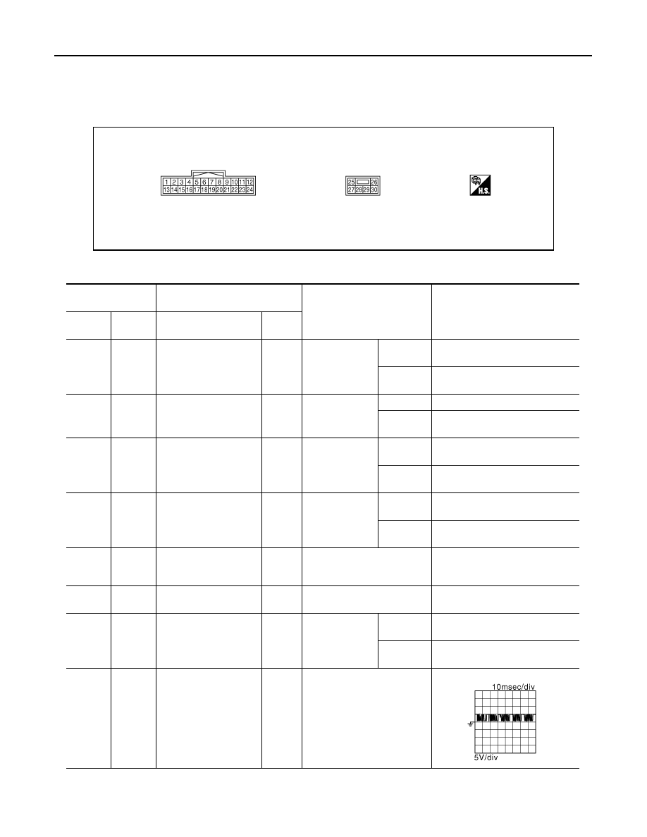
TERMINAL LAYOUT

PHYSICAL VALUES

JMJIA1389ZZ

Terminal No.

(wire color)

Description

Condition

Voltage (V)

(Approx.)

+

-

Signal name

Input/

Output

1

(Y)

Ground

Tilt switch up signal

Input

Tilt switch

Operate
(up)

0

Other than 
above

5

2

(GR)

Ground

Changeover switch RH
signal

Input

Changeover 
switch position

RH

0

Neutral or 
LH

5

3

(SB)

Ground

Mirror switch up signal

Input

Mirror switch

Operated
(up)

0

Other than 
above

5

4

(LG)

Ground

Mirror switch left signal

Input

Mirror switch

Operated
(left)

0

Other than 
above

5

5

(R)

Ground

Door mirror sensor (pas-
senger side) up/down 
signal

Input

Door mirror RH position

Change between 3.4 (close to 

peak) 0.6 (close to valley)

6

(Y)

Ground

Door mirror sensor (driv-
er side) up/down signal

Input

Door mirror LH position

Change between 3.4 (close to 

peak) 0.6 (close to valley)

7

(P)

Ground

Telescopic switch for-
ward signal

Input

Telescopic 
switch

Operate
(forward)

0

Other than 
above

5

8

(LG)

Ground

UART communication 
(TX/RX)

Output

Ignition switch ON

JMJIA1391ZZ

Revision: 2013 February

2012 MURANO

AUTOMATIC DRIVE POSITIONER CONTROL UNIT

MIR-29

< ECU DIAGNOSIS INFORMATION >

[WITH ADP]

C

D

E

F

G

H

I

J

K

M

A

B

MIR

N

O

P

10

(GR)

Ground

Door mirror motor (pas-
senger side) up output 
signal

Output

Door mirror RH

Operate
(up)

Battery voltage

Other than 
above

0

11

(G)

Ground

Door mirror motor (pas-
senger side) left output 
signal

Output

Door mirror RH

Operate
(left)

Battery voltage

Other than 
above

0

12

(R)

Ground

Door mirror motor (driv-
er side) down output sig-
nal

Output

Door mirror (LH)

Operate
(down)

Battery voltage

Other than 
above

0

Door mirror motor (driv-
er side) right output sig-
nal

Operate
(right)

Battery voltage

Other than 
above

0

13

(LG)

Ground

Tilt switch down signal

Input

Tilt switch

Operate
(down)

0

Other than 
above

5

14

(BG)

Ground

Changeover switch LH
signal

Input

Changeover 
switch position

LH

0

Neutral or 
RH

5

15

(L)

Ground

Mirror switch down sig-
nal

Input

Mirror switch

Operate
(down)

0

Other than 
above

5

16

(V)

Ground

Mirror switch right signal

Input

Mirror switch

Operate
(right)

0

Other than 
above

5

17

(W)

Ground

Door mirror sensor (pas-
senger side) left/right 
signal

Input

Door mirror RH position

Change between 3.4 (close to left 

edge) 0.6 (close to right edge)

18

(L)

Ground

Door mirror sensor (driv-
er side) left/right signal

Input

Door mirror LH position

Change between 0.6 (close to left 

edge) 3.4 (close to right edge)

19

(G)

Ground

Telescopic switch back-
ward signal

Input

Telescopic 
switch

Operate
(back-
ward)

0

Other than 
above

5

20

(Y)

Ground

Ground

0

21

(W)

Ground

Door mirror motor sen-
sor power supply

Input

Terminal No.

(wire color)

Description

Condition

Voltage (V)

(Approx.)

+

-

Signal name

Input/

Output

Revision: 2013 February

2012 MURANO

MIR-30

< ECU DIAGNOSIS INFORMATION >

[WITH ADP]

AUTOMATIC DRIVE POSITIONER CONTROL UNIT

22

(V)

Ground

Door mirror motor (pas-
senger side) down out-
put signal

Output

Door mirror (RH)

Operate
(down)

Battery voltage

Other than 
above

0

Door mirror motor (pas-
senger side) right output 
signal

Operate
(right)

Battery voltage

Other than 
above

0

23

(L)

Ground

Door mirror motor (driv-
er side)up output signal

Output

Door mirror (LH)

Operate
(up)

Battery voltage

Other than 
above

0

24

(SB)

Ground

Door mirror motor (driv-
er side)left output signal

Output

Door mirror (LH)

Operate
(left)

Battery voltage

Other than 
above

0

25

(W)

Ground

Power source 

Input

Battery voltage

26

(L)

Ground

Telescopic motor back-
ward output signal

Output

Steering tele-
scopic

Operate
(back-
ward)

Battery voltage

Other than 
above

0

27

(P)

Ground

Tilt&telescopic motor 
power source 

Battery voltage

28

(G)

Ground

Tilt motor down output 
signal

Output

Steering tilt

Operate
(down)

Battery voltage

Other than 
above

0

29

(LG)

Ground

Tilt motor up output sig-
nal

Output

Steering tilt

Operate
(up)

Battery voltage

Other than 
above

0

Telescopic motor for-
ward output signal

Steering tele-
scopic

Operate
(forward)

Battery voltage

Other than 
above

0

30

(B)

Ground

Ground

0

Terminal No.

(wire color)

Description

Condition

Voltage (V)

(Approx.)

+

-

Signal name

Input/

Output

Revision: 2013 February

2012 MURANO

AUTOMATIC DRIVE POSITIONER CONTROL UNIT

MIR-31

< ECU DIAGNOSIS INFORMATION >

[WITH ADP]

C

D

E

F

G

H

I

J

K

M

A

B

MIR

N

O

P

Wiring Diagram - AUTOMATIC DRIVE POSITIONER CONTROL SYSTEM -

INFOID:0000000007688437

For connector terminal arrangements, harness layouts, and alphabets in a

(option abbreviation; if not

described in wiring diagram), refer to 

GI-12, "Connector Information"

.

JRJWC0297GB

Revision: 2013 February

2012 MURANO

MIR-32

< ECU DIAGNOSIS INFORMATION >

[WITH ADP]

AUTOMATIC DRIVE POSITIONER CONTROL UNIT

JRJWC0298GB

Revision: 2013 February

2012 MURANO

AUTOMATIC DRIVE POSITIONER CONTROL UNIT

MIR-33

< ECU DIAGNOSIS INFORMATION >

[WITH ADP]

C

D

E

F

G

H

I

J

K

M

A

B

MIR

N

O

P

JRJWC0299GB

Revision: 2013 February

2012 MURANO

MIR-34

< SYMPTOM DIAGNOSIS >

[WITH ADP]

DOOR MIRROR DOES NOT OPERATE

SYMPTOM DIAGNOSIS

DOOR MIRROR DOES NOT OPERATE

Diagnosis Procedure

INFOID:0000000007540675

1.

CHECK AUTOMATIC DRIVE POSITIONER SYSTEM

Check door mirror operate with automatic drive positioner system.

Is the inspection result normal?

YES

>> GO TO 2.

NO

>> Check automatic drive positioner system operation. Refer to 

ADP-13, "AUTOMATIC DRIVE

POSITIONER SYSTEM : System Description"

2.

CHECK MIRROR SWITCH

Check door mirror remote control switch (mirror switch).
Refer to 

MIR-11, "MIRROR SWITCH : Component Function Check"

Is the inspection result normal?

YES

>> GO TO 3.

NO

>> Repair or replace the malfunctioning parts.

3.

CHECK CHANGEOVER SWITCH

Check door mirror remote control switch (changeover switch).
Refer to 

MIR-13, "CHANGEOVER SWITCH : Component Function Check"

Is the inspection result normal?

YES

>> GO TO 4.

NO

>> Repair or replace the malfunctioning parts.

4.

CONFIRM THE OPERATION

Confirm the operation again.
Is the result normal?

YES

>> Check intermittent incident. Refer to 

GI-44, "Intermittent Incident"

NO

>> GO TO 1.

Revision: 2013 February

2012 MURANO

SQUEAK AND RATTLE TROUBLE DIAGNOSES

MIR-35

< SYMPTOM DIAGNOSIS >

[WITH ADP]

C

D

E

F

G

H

I

J

K

M

A

B

MIR

N

O

P

SQUEAK AND RATTLE TROUBLE DIAGNOSES

Work Flow

INFOID:0000000007540676

CUSTOMER INTERVIEW

Interview the customer if possible, to determine the conditions that exist when the noise occurs. Use the Diag-
nostic Worksheet during the interview to document the facts and conditions when the noise occurs and any of
customer's comments; refer to 

MIR-39, "Diagnostic Worksheet"

. This information is necessary to duplicate the

conditions that exist when the noise occurs.
• The customer may not be able to provide a detailed description or the location of the noise. Attempt to obtain

all the facts and conditions that exist when the noise occurs (or does not occur).

• If there is more than one noise in the vehicle, perform a diagnosis and repair the noise that the customer is

concerned about. This can be accomplished by performing a cruise test on the vehicle with the customer.

• After identifying the type of noise, isolate the noise in terms of its characteristics. The noise characteristics

are provided so the customer, service adviser and technician are all speaking the same language when
defining the noise.

• Squeak – (Like tennis shoes on a clean floor)

Squeak characteristics include the light contact/fast movement/brought on by road conditions/hard surfaces
= higher pitch noise/softer surfaces = lower pitch noises/edge to surface = chirping

• Creak – (Like walking on an old wooden floor)

Creak characteristics include firm contact/slow movement/twisting with a rotational movement/pitch depen-
dent on materials/often brought on by activity.

• Rattle – (Like shaking a baby rattle)

Rattle characteristics include the fast repeated contact/vibration or similar movement/loose parts/missing
clip or fastener/incorrect clearance.

• Knock – (Like a knock on a door)

Knock characteristics include hollow sounding/sometimes repeating/often brought on by driver action.

• Tick – (Like a clock second hand)

Tick characteristics include gentle contacting of light materials/loose components/can be caused by driver
action or road conditions.

• Thump – (Heavy, muffled knock noise)

Thump characteristics include softer knock/dead sound often brought on by activity.

• Buzz – (Like a bumblebee)

Buzz characteristics include high frequency rattle/firm contact.

• Often the degree of acceptable noise level will vary depending up on the person. A noise that a technician

may judge as acceptable may be very irritating to the customer.

• Weather conditions, especially humidity and temperature, may have a great effect on noise level.

DUPLICATE THE NOISE AND TEST DRIVE

If possible, drive the vehicle with the customer until the noise is duplicated. Note any additional information on
the Diagnostic Worksheet regarding the conditions or location of the noise. This information can be used to
duplicate the same conditions when the repair is reconfirmed.

SBT842

Revision: 2013 February

2012 MURANO

MIR-36

< SYMPTOM DIAGNOSIS >

[WITH ADP]

SQUEAK AND RATTLE TROUBLE DIAGNOSES

If the noise can be duplicated easily during the test drive, to help identify the source of the noise, try to dupli-
cate the noise with the vehicle stopped by doing one or all of the following:
1) Close a door.
2) Tap or push/pull around the area where the noise appears to be coming from.
3) Rev the engine.
4) Use a floor jack to recreate vehicle “twist”.
5) At idle, apply engine load (electrical load, half-clutch on M/T models, drive position on A/T models).
6) Raise the vehicle on a hoist and hit a tire with a rubber hammer.
• Drive the vehicle and attempt to duplicate the conditions the customer states exist when the noise occurs.
• If it is difficult to duplicate the noise, drive the vehicle slowly on an undulating or rough road to stress the

vehicle body.

CHECK RELATED SERVICE BULLETINS

After verifying the customer concern or symptom, check ASIST for Technical Service Bulletins (TSBs) related
to that concern or symptom.
If a TSB relates to the symptom, follow the procedure to repair the noise.

LOCATE THE NOISE AND IDENTIFY THE ROOT CAUSE

1.

Narrow down the noise to a general area. To help pinpoint the source of the noise, use a listening tool
(Chassis ear: J-39570, Engine ear and mechanics stethoscope).

2.

Narrow down the noise to a more specific area and identify the cause of the noise by:

• Removing the components in the area that is are suspected to be the cause of the noise.

Do not use too much force when removing clips and fasteners, otherwise clips and fastener can be broken
or lost during the repair, resulting in the creation of new noise.

• Tapping or pushing/pulling the component that is are suspected to be the cause of the noise.

Do not tap or push/pull the component with excessive force, otherwise the noise will be eliminated only tem-
porarily.

• Feeling for a vibration by hand by touching the component(s) that is are suspected to be the cause of the

noise.

• Placing a piece of paper between components that are suspected to be the cause of the noise.
• Looking for loose components and contact marks.

Refer to 

MIR-37, "Inspection Procedure"

.

REPAIR THE CAUSE

• If the cause is a loose component, tighten the component securely.
• If the cause is insufficient clearance between components:
- Separate components by repositioning or loosening and retightening the component, if possible.
- Insulate components with a suitable insulator such as urethane pads, foam blocks, felt cloth tape or ure-

thane tape. A Nissan Squeak and Rattle Kit (J-43980) is available through the authorized Nissan Parts
Department.

CAUTION:

Never use excessive force as many components are constructed of plastic and may be damaged.
NOTE:
Always check with the Parts Department for the latest parts information.
The following materials are contained in the Nissan Squeak and Rattle Kit (J-43980). Each item can be
ordered separately as needed.
URETHANE PADS [1.5 mm (0.059 in) thick]
Insulates connectors, harness, etc.
76268-9E005: 100

×

135 mm (3.94

×

5.31 in)/76884-71L01: 60

×

85 mm (2.36

×

3.35 in)/76884-

71L02:15

×

25 mm (0.59

×

0.98 in)

INSULATOR (Foam blocks)
Insulates components from contact. Can be used to fill space behind a panel.
73982-9E000: 45 mm (1.77 in) thick, 50

×

50 mm (1.97

×

1.97 in)/73982-

50Y00: 10 mm (0.39 in) thick, 50

×

50 mm (1.97

×

1.97 in)

INSULATOR (Light foam block)
80845-71L00: 30 mm (1.18 in) thick, 30

×

50 mm (1.18

×

1.97in)

FELT CLOTHTAPE
Used to insulate where movement does not occur. Ideal for instrument panel applications.
68370-4B000: 15

×

25 mm (0.59

×

0.98 in) pad/68239-13E00: 5 mm (0.20 in) wide tape roll

The following materials, not found in the kit, can also be used to repair squeaks and rattles.
UHMW (TEFLON) TAPE

Revision: 2013 February

2012 MURANO

SQUEAK AND RATTLE TROUBLE DIAGNOSES

MIR-37

< SYMPTOM DIAGNOSIS >

[WITH ADP]

C

D

E

F

G

H

I

J

K

M

A

B

MIR

N

O

P

Insulates where slight movement is present. Ideal for instrument panel applications.
SILICONE GREASE
Used in place of UHMW tape that is be visible or does not fit. Will only last a few months.
SILICONE SPRAY
Used when grease cannot be applied.
DUCT TAPE
Used to eliminate movement.

CONFIRM THE REPAIR

Confirm that the cause of a noise is repaired by test driving the vehicle. Operate the vehicle under the same
conditions as when the noise originally occurred. Refer to the notes on the Diagnostic Worksheet.

Inspection Procedure

INFOID:0000000007540677

Refer to Table of Contents for specific component removal and installation information.

INSTRUMENT PANEL

Most incidents are caused by contact and movement between:

1.

The cluster lid A and instrument panel

2.

Acrylic lens and combination meter housing

3.

Instrument panel to front pillar garnish

4.

Instrument panel to windshield

5.

Instrument panel mounting pins

6.

Wiring harnesses behind the combination meter

7.

A/C defroster duct and duct joint
These incidents can usually be located by tapping or moving the components to duplicate the noise or by
pressing on the components while driving to stop the noise. Most of these incidents can be repaired by
applying felt cloth tape or silicon spray (in hard to reach areas). Urethane pads can be used to insulate
wiring harness.

CAUTION:

Never use silicone spray to isolate a squeak or rattle. If the area is saturated with silicone, the
recheck of repair becomes impossible.

CENTER CONSOLE

Components to pay attention to include:

1.

Shifter assembly cover to finisher

2.

A/C control unit and cluster lid C

3.

Wiring harnesses behind audio and A/C control unit

The instrument panel repair and isolation procedures also apply to the center console.

DOORS

Pay attention to the following:

1.

Finisher and inner panel making a slapping noise

2.

Inside handle escutcheon to door finisher

3.

Wiring harnesses tapping

4.

Door striker out of alignment causing a popping noise on starts and stops

Tapping or moving the components or pressing on them while driving to duplicate the conditions can isolate
many of these incidents. The areas can usually be insulated with felt cloth tape or insulator foam blocks from
the Nissan Squeak and Rattle Kit (J-43980) to repair the noise.

TRUNK

Trunk noises are often caused by a loose jack or loose items put into the trunk by the customer.
In addition look for the following:
1.

Trunk lid dumpers out of adjustment

2.

Trunk lid striker out of adjustment

3.

The trunk lid torsion bars knocking together

4.

A loose license plate or bracket

Revision: 2013 February

2012 MURANO

MIR-38

< SYMPTOM DIAGNOSIS >

[WITH ADP]

SQUEAK AND RATTLE TROUBLE DIAGNOSES

Most of these incidents can be repaired by adjusting, securing or insulating the item(s) or component(s) caus-
ing the noise.

SUNROOF/HEADLINING

Noises in the sunroof/headlining area can often be traced to one of the following:

1.

Sunroof lid, rail, linkage or seals making a rattle or light knocking noise

2.

Sunvisor shaft shaking in the holder

3.

Front or rear windshield touching headlining and squeaking

Again, pressing on the components to stop the noise while duplicating the conditions can isolate most of these
incidents. Repairs usually consist of insulating with felt cloth tape.

SEATS

When isolating seat noise it's important to note the position the seats in and the load placed on the seat when
the noise occurs. These conditions should be duplicated when verifying and isolating the cause of the noise.
Cause of seat noise include:

1.

Headrest rods and holder

2.

A squeak between the seat pad cushion and frame

3.

The rear seatback lock and bracket

These noises can be isolated by moving or pressing on the suspected components while duplicating the con-
ditions under which the noise occurs.Most of these incidents can be repaired by repositioning the component
or applying urethane tape to the contact area.

UNDERHOOD

Some interior noise may be caused by components under the hood or on the engine wall. The noise is then
transmitted into the passenger compartment.
Causes of transmitted underhood noise include:

1.

Any component mounted to the engine wall

2.

Components that pass through the engine wall

3.

Engine wall mounts and connectors

4.

Loose radiator mounting pins

5.

Hood bumpers out of adjustment

6.

Hood striker out of adjustment

These noises can be difficult to isolate since they cannot be reached from the interior of the vehicle. The best
method is to secure, move or insulate one component at a time and test drive the vehicle. Also, engine RPM
or load can be changed to isolate the noise. Repairs can usually be made by moving, adjusting, securing, or
insulating the component causing the noise.

Revision: 2013 February

2012 MURANO

SQUEAK AND RATTLE TROUBLE DIAGNOSES

MIR-39

< SYMPTOM DIAGNOSIS >

[WITH ADP]

C

D

E

F

G

H

I

J

K

M

A

B

MIR

N

O

P

Diagnostic Worksheet

INFOID:0000000007540678

PIIB8740E

Revision: 2013 February

2012 MURANO

MIR-40

< SYMPTOM DIAGNOSIS >

[WITH ADP]

SQUEAK AND RATTLE TROUBLE DIAGNOSES

PIIB8742E

Revision: 2013 February

2012 MURANO

PRECAUTIONS

MIR-41

< PRECAUTION >

[WITH ADP]

C

D

E

F

G

H

I

J

K

M

A

B

MIR

N

O

P

PRECAUTION

PRECAUTIONS

FOR USA AND CANADA

FOR USA AND CANADA : Precaution for Supplemental Restraint System (SRS) "AIR 
BAG" and "SEAT BELT PRE-TENSIONER"

INFOID:0000000007540679

The Supplemental Restraint System such as “AIR BAG” and “SEAT BELT PRE-TENSIONER”, used along
with a front seat belt, helps to reduce the risk or severity of injury to the driver and front passenger for certain
types of collision. This system includes seat belt switch inputs and dual stage front air bag modules. The SRS
system uses the seat belt switches to determine the front air bag deployment, and may only deploy one front
air bag, depending on the severity of a collision and whether the front occupants are belted or unbelted.
Information necessary to service the system safely is included in the “SRS AIR BAG” and “SEAT BELT” of this
Service Manual.

WARNING:

Always observe the following items for preventing accidental activation.
• To avoid rendering the SRS inoperative, which could increase the risk of personal injury or death in

the event of a collision that would result in air bag inflation, all maintenance must be performed by
an authorized NISSAN/INFINITI dealer.

• Improper maintenance, including incorrect removal and installation of the SRS, can lead to personal

injury caused by unintentional activation of the system. For removal of Spiral Cable and Air Bag
Module, see “SRS AIR BAG”.

• Never use electrical test equipment on any circuit related to the SRS unless instructed to in this Ser-

vice Manual. SRS wiring harnesses can be identified by yellow and/or orange harnesses or harness
connectors.

PRECAUTIONS WHEN USING POWER TOOLS (AIR OR ELECTRIC) AND HAMMERS

WARNING:

Always observe the following items for preventing accidental activation.
• When working near the Air Bag Diagnosis Sensor Unit or other Air Bag System sensors with the

ignition ON or engine running, never use air or electric power tools or strike near the sensor(s) with
a hammer. Heavy vibration could activate the sensor(s) and deploy the air bag(s), possibly causing
serious injury.

• When using air or electric power tools or hammers, always switch the ignition OFF, disconnect the

battery, and wait at least 3 minutes before performing any service.

FOR USA AND CANADA : Precaution for Procedure without Cowl Top Cover

INFOID:0000000007540680

When performing the procedure after removing cowl top cover, cover
the lower end of windshield with urethane, etc to prevent damage to
windshield.

FOR USA AND CANADA : Precaution for Work

INFOID:0000000007540681

• After removing and installing the opening/closing parts, be sure to carry out fitting adjustments to check their

operation.

• Check the lubrication level, damage, and wear of each part. If necessary, grease or replace it.

FOR MEXICO

FOR MEXICO : Precaution for Supplemental Restraint System (SRS) "AIR BAG" and 

PIIB3706J

Revision: 2013 February

2012 MURANO

MIR-42

< PRECAUTION >

[WITH ADP]

PRECAUTIONS

"SEAT BELT PRE-TENSIONER"

INFOID:0000000007540682

The Supplemental Restraint System such as “AIR BAG” and “SEAT BELT PRE-TENSIONER”, used along
with a front seat belt, helps to reduce the risk or severity of injury to the driver and front passenger for certain
types of collision. Information necessary to service the system safely is included in the “SRS AIR BAG” and
“SEAT BELT” of this Service Manual.

WARNING:

Always observe the following items for preventing accidental activation.
• To avoid rendering the SRS inoperative, which could increase the risk of personal injury or death in

the event of a collision that would result in air bag inflation, all maintenance must be performed by
an authorized NISSAN/INFINITI dealer.

• Improper maintenance, including incorrect removal and installation of the SRS, can lead to personal

injury caused by unintentional activation of the system. For removal of Spiral Cable and Air Bag
Module, see “SRS AIR BAG”.

• Never use electrical test equipment on any circuit related to the SRS unless instructed to in this Ser-

vice Manual. SRS wiring harnesses can be identified by yellow and/or orange harnesses or harness
connectors.

PRECAUTIONS WHEN USING POWER TOOLS (AIR OR ELECTRIC) AND HAMMERS

WARNING:

Always observe the following items for preventing accidental activation.
• When working near the Air Bag Diagnosis Sensor Unit or other Air Bag System sensors with the

ignition ON or engine running, never use air or electric power tools or strike near the sensor(s) with
a hammer. Heavy vibration could activate the sensor(s) and deploy the air bag(s), possibly causing
serious injury.

• When using air or electric power tools or hammers, always switch the ignition OFF, disconnect the

battery, and wait at least 3 minutes before performing any service.

FOR MEXICO : Precaution for Procedure without Cowl Top Cover

INFOID:0000000007540683

When performing the procedure after removing cowl top cover, cover
the lower end of windshield with urethane, etc to prevent damage to
windshield.

FOR MEXICO : Precaution for Work

INFOID:0000000007540684

• After removing and installing the opening/closing parts, be sure to carry out fitting adjustments to check their

operation.

• Check the lubrication level, damage, and wear of each part. If necessary, grease or replace it.

PIIB3706J

Revision: 2013 February

2012 MURANO

PREPARATION

MIR-43

< PREPARATION >

[WITH ADP]

C

D

E

F

G

H

I

J

K

M

A

B

MIR

N

O

P

PREPARATION

PREPARATION

Special Service Tools

INFOID:0000000007540685

The actual shapes of Kent-Moore tools may differ from those of special service tools illustrated here.

Commercial Service Tools

INFOID:0000000007540686

Tool number

(Kent-Moore No.)

Tool name

Description

(J-39570)
Chassis ear

Locates the noise

(J-43980)
NISSAN Squeak and Rat-
tle Kit

Repairs the cause of noise

SIIA0993E

SIIA0994E

Tool name

Description

Engine ear

Locates the noise

Remover tool

Removes the clips, pawls, and metal clips

Power tool

SIIA0995E

JMKIA3050ZZ

PIIB1407E

Revision: 2013 February

2012 MURANO


Content      ..     51      52      53      54     ..