Nissan Murano Z51 (2011 year). Manual - part 9
BR-38
< REMOVAL AND INSTALLATION >
FRONT DISC BRAKE
5.
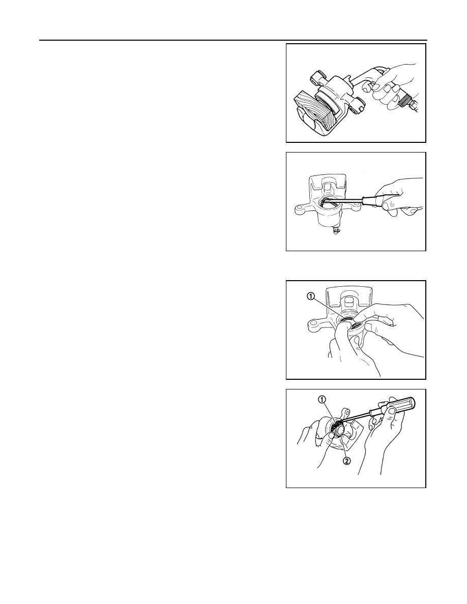
Place a wooden block as shown in the figure, and blow air from
union bolt mounting hole to remove piston and piston boot.
CAUTION:
Never get fingers caught in the piston.
6.
Remove piston seal from cylinder body using suitable tool.
CAUTION:
Be careful not to damage a cylinder inner wall.
7.
Remove bleeder valve and cap.
ASSEMBLY
1.
Install bleeder valve and cap.
2.
Apply polyglycol ether based lubricant to piston seal (1), and
install to cylinder body.
CAUTION:
Never reuse piston seal.
3.
Apply rubber grease to piston boot (1). Cover the piston (2) end
with piston boot, and then install cylinder side lip on piston boot
securely into a groove on cylinder body.
CAUTION:
Never reuse piston boot.
MAA0272D
JPFIA0038ZZ
JPFIA0039ZZ
JPFIA0040ZZ
Revision: 2011 November
2011 MURANO