Nissan Murano Z50 (2007 year). Manual - part 184


  Index      Manuals     Nissan Murano Z50 (2007 year) - Service and Repair Manual


Search            copyright infringement  


Content      ..     182      183      184      185     ..


Nissan Murano Z50 (2007 year). Manual - part 184


TROUBLE DIAGNOSIS

SRS-19

C

D

E

F

G

I

J

K

L

M

A

B

SRS

Revision: 2006 July

2007 Murano

CONSULT-II Function

NHS0005I

DIAGNOSIS MODE FOR CONSULT-II

“SELF-DIAG [CURRENT]”
A current self-diagnostic results (also indicated by the number of warning lamp flashes in the Diagnosis
mode) is displayed on the CONSULT-II screen in real time. This refers to a malfunctioning part requiring
repairs.

“SELF-DIAG [PAST]”
Diagnosis results previously stored in the memory are displayed on the CONSULT-II screen. The stored
results are not erased until memory erasing is executed.

“TROUBLE DIAG RECORD”
With TROUBLE DIAG RECORD, diagnosis results previously erased by a reset operation can be dis-
played on the CONSULT-II screen.

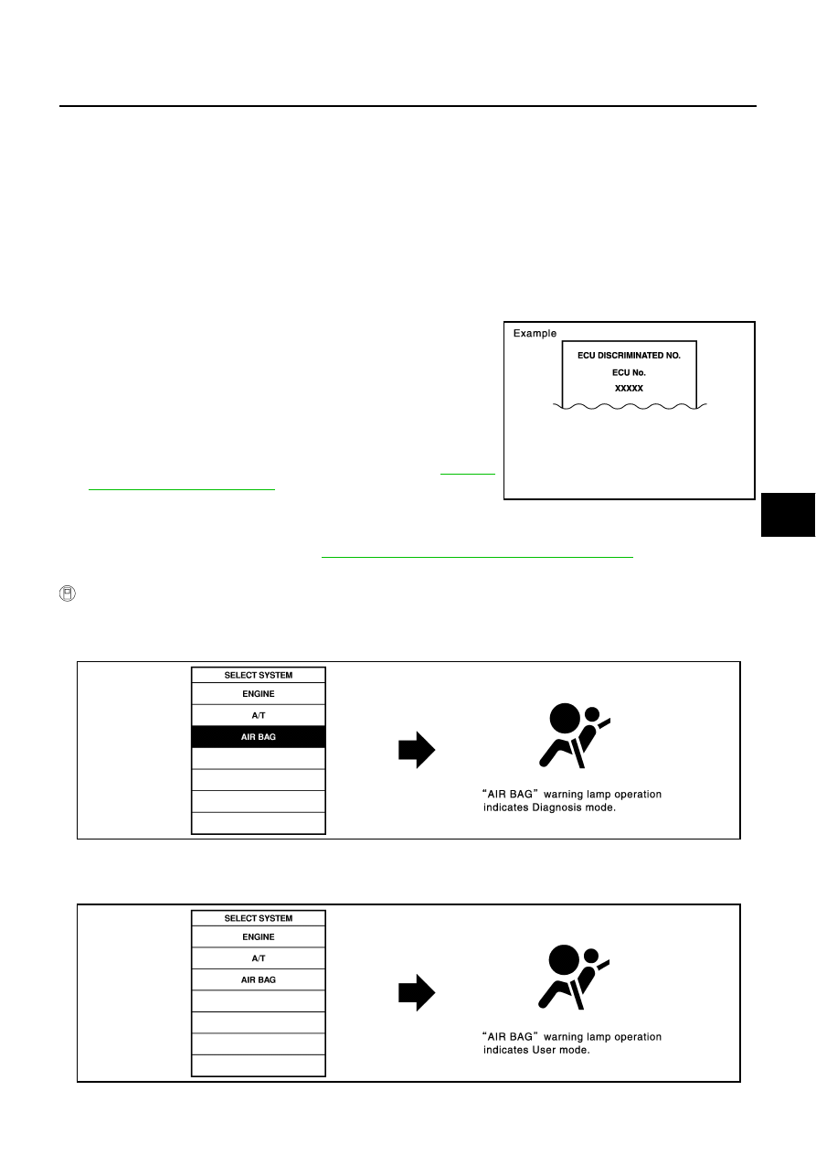
“ECU DISCRIMINATED NO.”
The diagnosis sensor unit for each vehicle model is assigned
with its own, individual classification number. This number will
be displayed on the CONSULT-II screen, as shown. When
replacing the diagnosis sensor unit, refer to the part number for
the compatibility. After installation, replacement with a correct
unit can be checked by confirming this classification number on
the CONSULT-II screen.
After repair, make sure the discriminated number of diagnosis
sensor unit installed to vehicle are same. Refer to 

SRS-54,

"ECU DISCRIMINATED NO."

 .

PASSENGER AIR BAG
The STATUS (readiness) of the front passenger air bag module is displayed. The STATUS displayed 
(ON/OFF) depends on the signals supplied to the occupant classification system control module and air
bag diagnosis sensor unit. Refer to 

SRS-7, "Occupant Classification System (OCS)"

  for more informa-

tion.

 HOW TO CHANGE SELF-DIAGNOSIS MODE WITH CONSULT-II

From User Mode to Diagnosis Mode

After selecting “AIR BAG” on the “SELECT SYSTEM” screen, User mode automatically changes to Diagnosis
mode.

From Diagnosis Mode to User Mode

To return to User mode from Diagnosis mode, touch “BACK” key of CONSULT-II until “SELECT SYSTEM”
appears, Diagnosis mode automatically changes to User mode.

PHIA0218E

SRS803

SRS804

SRS-20

TROUBLE DIAGNOSIS

Revision: 2006 July

2007 Murano

HOW TO ERASE SELF-DIAGNOSTIC RESULTS

“SELF-DIAG [CURRENT]”
A current self-diagnostic result is displayed on the CONSULT-II screen in real time.
After the malfunction is repaired completely, no malfunction is detected on “SELF-DIAG [CURRENT]”.

“SELF-DIAG [PAST]”
Return to the “SELF-DIAG [CURRENT]” CONSULT-II screen by touching “BACK” key of CONSULT-II and
select “SELF-DIAG [CURRENT]” in SELECT DIAG MODE. Touch “ERASE” in “SELF-DIAG [CURRENT]”
mode.

NOTE:
If the memory of the malfunction in “SELF-DIAG [PAST]” is not erased, the User mode shows the system
malfunction by the operation of the warning lamp even if the malfunction is repaired completely.

“TROUBLE DIAG RECORD”
The memory of “TROUBLE DIAG RECORD” cannot be erased.

Self-Diagnosis Function (Without CONSULT-II)

NHS0005J

The reading of these results is accomplished “User mode” and “Diagnosis mode”.

After a malfunction is repaired, turn ignition switch ON. Diagnosis mode returns to the User mode. At that
time, the self-diagnostic result is cleared.

HOW TO CHANGE SELF-DIAGNOSIS MODE WITHOUT CONSULT-LL

HOW TO ERASE SELF-DIAGNOSTIC RESULTS

After a malfunction is repaired, turn the ignition switch OFF for at least one second, then back ON. Diagnosis
mode returns to the User mode. At that time, the self-diagnostic result is cleared.

SRS701

PHIA0709E

TROUBLE DIAGNOSIS

SRS-21

C

D

E

F

G

I

J

K

L

M

A

B

SRS

Revision: 2006 July

2007 Murano

SRS Operation Check

NHS0005K

DIAGNOSTIC PROCEDURE 1
Checking Air Bag Operation by Using “AIR BAG” Warning Lamp — User Mode

1.

Turn the ignition switch from OFF to ON, and make sure the air bag warning lamp blinks.

2.

Compare the SRS air bag warning lamp blinking pattern with the
examples.

BF-1845D

SRS-22

TROUBLE DIAGNOSIS

Revision: 2006 July

2007 Murano

Warning lamp examples

“AIR BAG” warning lamp operation — User mode

SRS condition

Reference item

No malfunction is detected.

No further action is necessary.

The system is malfunctioning and 
needs to be repaired as indicated.

Go to 

SRS-23, "DIAGNOSTIC 

PROCEDURE 2"

   or 

SRS-30, 

"DIAGNOSTIC PROCEDURE 5"

 .

Air bag is deployed.

Seat belt pre-tensioner is deployed.

Go to 

SRS-56, "COLLISION DIAG-

NOSIS"

 .

Diagnosis sensor unit is malfunction-
ing.

Air bag power supply circuit is mal-
functioning.

SRS air bag warning lamp circuit is 
malfunctioning.

Go to 

SRS-40, "Trouble Diagnosis: 

“AIR BAG” Warning Lamp Does Not 
Turn OFF"

 .

Diagnosis sensor unit is malfunction-
ing.

Air bag warning lamp circuit is mal-
functioning.

Go to 

SRS-41, "Trouble Diagnosis: 

“AIR BAG” Warning Lamp Does Not 
Turn ON"

 .

SHIA0011E

SHIA0012E

SHIA0013E

SHIA0014E

TROUBLE DIAGNOSIS

SRS-23

C

D

E

F

G

I

J

K

L

M

A

B

SRS

Revision: 2006 July

2007 Murano

Trouble Diagnosis with CONSULT-II

NHS0005L

DIAGNOSTIC PROCEDURE 2

Refer to 

GI-37, "CONSULT-II Start Procedure"

 .

CAUTION:

If CONSULT-II is used with no connection of CONSULT-II CONVERTER, malfunctions might be
detected in self-diagnosis depending on control unit which carry out CAN communication.

1.

Touch “SELF-DIAG [CURRENT]”.

2.

Diagnostic code is displayed on “SELF-DIAG [CURRENT]”.

3.

If no malfunction is detected on “SELF-DIAG [CURRENT]” even
though malfunction is detected in “SRS Operation Check”,
check the battery voltage. If the battery voltage is less than 9V,
charge or replace the battery. Then go to 

SRS-28, "DIAGNOS-

TIC PROCEDURE 3"

 . If the battery voltage is OK, go to 

SRS-

30, "DIAGNOSTIC PROCEDURE 4 (CONTINUED FROM
DIAGNOSTIC PROCEDURE 2)"

  to diagnose the following

cases:

Self-diagnostic result “SELF-DIAG [PAST]” (previously stored
in the memory) might not be erased after repair.

The SRS system malfunctions intermittently.

DTC No. Index (“SELF-DIAG [CURRENT]”)

SRS697

SHIA0203E

SRS701

Diagnostic item

Explanation

Repair order

“Recheck SRS at each replacement”

NO DTC IS 

DETECTED.

When malfunction is 
indicated by the “AIR 
BAG” warning lamp in 
User mode.

Low battery voltage (Less than 9V)

Go to 

SRS-28, "DIAGNOSTIC PRO-

CEDURE 3"

  after charging the bat-

tery.

Self-diagnostic result “SELF-DIAG 
[PAST]” (previously stored in the 
memory) might not be erased after 
repair.

Intermittent malfunction has been 
detected in the past.

Go to 

SRS-30, "DIAGNOSTIC PRO-

CEDURE 4 (CONTINUED FROM 
DIAGNOSTIC PROCEDURE 2)"

 .

Go to 

SRS-30, "DIAGNOSTIC PRO-

CEDURE 5"

 .

No malfunction is detected.

SRS-24

TROUBLE DIAGNOSIS

Revision: 2006 July

2007 Murano

DRIVER AIRBAG 
MODULE
[OPEN]
[B1054]

Driver air bag module circuit is open (including the spiral cable).

1. Visually check the wiring harness 

connection.

2. Replace the harness if it has visible 

damage.

3. Replace the driver air bag module. 

4. Replace the spiral cable.

5. Replace the diagnosis sensor unit.

6. Replace the related harness.

DRIVER AIRBAG 
MODULE
[VB-SHORT]
[B1055]

Driver air bag module circuit is shorted to a power supply circuit 
(including the spiral cable).

DRIVER AIRBAG 
MODULE
[GND-SHORT]
[B1056]

Driver air bag module circuit is shorted to ground (including the 
spiral cable).

DRIVER AIRBAG 
MODULE
[SHORT]
[B1057]

Driver air bag module circuit is shorted between lines.

ASSIST A/B MODULE
[OPEN]
[B1070]

Front passenger air bag module circuit is open.

1. Visually check the wiring harness 

connection.

2. Replace the harness if it has visible 

damage.

3. Replace the front passenger air bag 

module.

4. Replace the diagnosis sensor unit.

5. Replace the related harness.

ASSIST A/B MODULE
[VB-SHORT]
[B1071]

Front passenger air bag module circuit is shorted to a power 
supply circuit.

ASSIST A/B MODULE
[GND-SHORT]
[B1072]

Front passenger air bag module circuit is shorted to ground.

ASSIST A/B MODULE
[SHORT]
[B1073]

Front passenger air bag module circuit is shorted between lines.

CRASH ZONE SEN
[UNIT FAIL]
[B1033]
[B1034]
CRASH ZONE SEN
[COMM FAIL]
[B1035]
CRASH ZONE SEN
[UNMATCH]
[B1036]

Crash zone sensor

1. Visually check the wiring harness 

connection.

2. Replace the harness if it has visible 

damage.

3. Replace the crash zone sensor.

4. Replace the diagnosis sensor unit.

5. Replace the related harness.

SIDE MODULE LH
[OPEN]
[B1134]

Front LH side air bag module circuit is open.

1. Visually check the wiring harness 

connection.

2. Replace the harness if it has visible 

damage.

3. Replace the front LH setback 

assembly (front LH side air bag 
module).

4. Replace the diagnosis sensor unit.

5. Replace the related harness.

SIDE MODULE LH
[VB-SHORT]
[B1135]

Front LH side air bag module circuit is shorted to a power sup-
ply circuit.

SIDE MODULE LH
[GND-SHORT]
[B1136]

Front LH side air bag module circuit is shorted to ground.

SIDE MODULE LH
[SHORT]
[B1137]

Front LH side air bag module circuit is shorted between lines.

Diagnostic item

Explanation

Repair order

“Recheck SRS at each replacement”

TROUBLE DIAGNOSIS

SRS-25

C

D

E

F

G

I

J

K

L

M

A

B

SRS

Revision: 2006 July

2007 Murano

SIDE MODULE RH
[OPEN]
[B1129]

Front RH side air bag module circuit is open.

1. Visually check the wiring harness 

connection.

2. Replace the harness if it has visible 

damage.

3. Replace the front RH setback 

assembly (front RH side air bag 
module).

4. Replace the diagnosis sensor unit.

5. Replace the related harness.

SIDE MODULE RH
[VB-SHORT]
[B1130]

Front RH side air bag module circuit is shorted to a power sup-
ply circuit.

SIDE MODULE RH
[GND-SHORT]
[B1131]

Front RH side air bag module circuit is shorted to ground.

SIDE MODULE RH
[SHORT]
[B1132]

Front RH side air bag module circuit is shorted between lines.

SATELLITE SENS LH
[UNIT FAIL]
[B1118]
[B1119]
SATELLITE SENS LH
[COMM FAIL]
[B1120]
SATELLITE SENS LH
[UNMATCH]
[B1121]

LH side air bag (Satellite) sensor

1. Visually check the wiring harness 

connection.

2. Replace the harness if it has visible 

damage.

3. Replace the LH side air bag (Satel-

lite) sensor.

4. Replace the diagnosis sensor unit.

5. Replace the related harness.

SATELLITE SENS RH
[UNIT FAIL]
[B1113]
[B1114]
SATELLITE SENS RH
[COMM FAIL]
[B1115]
SATELLITE SENS RH
[UNMATH]
[B1116]

RH side air bag (Satellite) sensor

1. Visually check the wiring harness 

connection.

2. Replace the harness if it has visible 

damage.

3. Replace the RH side air bag (Satel-

lite) sensor.

4. Replace the diagnosis sensor unit.

5. Replace the related harness.

PRE-TEN FRONT LH
[OPEN]
[B1086]

Front LH pre-tensioner circuit is open. 

1. Visually check the wiring harness 

connections.

2. Replace the harness if it has visible 

damage.

3. Replace the front LH seat belt.

4. Replace the diagnosis sensor unit.

5. Replace the related harness.

PRE-TEN FRONT LH
[VB-SHORT]
[B1087]

Front LH pre-tensioner circuit is shorted to a power supply cir-
cuit.

PRE-TEN FRONT LH
[GND-SHORT]
[B1088]

Front LH pre-tensioner circuit is shorted to ground.

PRE-TEN FRONT LH
[SHORT]
[B1089]

Front LH pre-tensioner circuit is shorted between lines.

PRE-TEN FRONT RH
[OPEN]
[B1081]

Front RH pre-tensioner circuit is open.

1. Visually check the wiring harness 

connections.

2. Replace the harness if it has visible 

damage.

3. Replace the front RH seat belt.

4. Replace the diagnosis sensor unit.

5. Replace the related harness.

PRE-TEN FRONT RH
[VB-SHORT]
[B1082]

Front RH pre-tensioner circuit is shorted to a power supply cir-
cuit.

PRE-TEN FRONT RH
[GND-SHORT]
[B1083]

Front RH pre-tensioner circuit is shorted to ground.

PRE-TEN FRONT RH
[SHORT]
[B1084]

Front RH pre-tensioner circuit is shorted between lines.

Diagnostic item

Explanation

Repair order

“Recheck SRS at each replacement”

SRS-26

TROUBLE DIAGNOSIS

Revision: 2006 July

2007 Murano

CURTAIN MODULE LH
[OPEN]
[B1150]

LH side curtain air bag module circuit is open.

1. Visually check the wiring harness 

connection.

2. Replace the harness if it has visible 

damage.

3. Replace the LH side curtain air bag 

module.

4. Replace the diagnosis sensor unit.

5. Replace the related harness.

CURTAIN MODULE LH
[VB-SHORT]
[B1151]

LH side curtain air bag module circuit is shorted to some power 
supply circuits.

CURTAIN MODULE LH
[GND-SHORT]
[B1152]

LH side curtain air bag module circuit is shorted to ground.

CURTAIN MODULE LH
[SHORT]
[B1153]

LH side curtain air bag module circuit is shorted between lines.

CURTAIN MODULE RH
[OPEN]
[B1145]

RH side curtain air bag module circuit is open.

1. Visually check the wiring harness 

connection.

2. Replace the harness if it has visible 

damage.

3. Replace the RH side curtain air bag 

module.

4. Replace the diagnosis sensor unit.

5. Replace the related harness.

CURTAIN MODULE RH
[VB-SHORT]
[B1146]

RH side curtain air bag module circuit is shorted to a power sup-
ply circuit.

CURTAIN MODULE RH
[GND-SHORT]
[B1147]

RH side curtain air bag module circuit is shorted to ground.

CURTAIN MODULE RH
[SHORT]
[B1148]

RH side curtain air bag module circuit is shorted between lines.

CONTROL UNIT
[B1001-B1015]
[B1026-B1031]
[B1042-B1047]
[B1058-B1063]
[B1074-B1079]
[B1106-B1111]
[B1122-B1127]
[B1138-B1143]
[B1202-B1207]

Diagnosis sensor unit is malfunctioning.

1. Visually check the wiring harness 

connection.

2. Replace the diagnosis sensor unit.

PASS A/B INDCTR 
CKT
[B1023]

Cutoff telltale circuit is open or shorted to grand or the circuits 
are shorted each other.

1. Visually check the wiring harness 

connection.

2. Replace the harness if it has visible 

damage.

3. Replace cutoff telltale.

4. Replace the diagnosis sensor unit.

OCCUPANT SENS C/U
[UNIT FAIL]
[B1017]
[B1020]
[B1021]

Trouble occurs in Occupant Classification System-CU.

Replace passenger side seat cush-
ion assembly.

OCCUPANT SENS C/U 
[COMM FAIL]
[B1022]

Trouble occurs in Occupant Classification System-CU, circuit of 
Occupant Classification System-CU—Diagnosis Senser Unit, or 
Diagnosis  Sensor Unit.

1. Visually check the wiring harness 

connection.

2. Replace the harness if it has visible 

damage.

3. Replace passenger side seat cush-

ion assembly.

4. Replace the diagnosis sensor unit.

OCCUPANT SENS
[UNIT FAIL]
[B1018]

Trouble occurs in Occupant Classification System-SENS.

Replace passenger side seat cush-
ion assembly.

Diagnostic item

Explanation

Repair order

“Recheck SRS at each replacement”

TROUBLE DIAGNOSIS

SRS-27

C

D

E

F

G

I

J

K

L

M

A

B

SRS

Revision: 2006 July

2007 Murano

NOTE:
Follow the procedures in numerical order when repairing malfunctioning parts. Confirm whether malfunction is
eliminated using air bag warning lamp or CONSULT-II each time repair is finished. If malfunction is still
observed, proceed to the next step. When malfunction is eliminated, further repair work is not required.    

BELT TENSION SENS
[UNIT FAIL]
[B1019]

Trouble occurs in Belt Tension sensor (BTS), circuit of BTS—
Occupant Classification System-CU, or Occupant Classification 
System-CU.

1. Visually check the wiring harness 

connection.

2. Replace the harness if it has visible 

damage.

3. Replace passenger side seat belt 

assembly.

4. Replace the diagnosis sensor unit.

FRONTAL COLLISION-
DETECTION
[B1209]

Seat belt pre-tensioner and front air bag are deployed.

Go to 

SRS-56, "For Frontal Colli-

sion"

 .

SIDE COLLISION 
DETECTION
[B1210]

Side and curtain air bag is deployed.

Go to 

SRS-58, "For Side Collision"

 .

Diagnostic item

Explanation

Repair order

“Recheck SRS at each replacement”

SRS-28

TROUBLE DIAGNOSIS

Revision: 2006 July

2007 Murano

DIAGNOSTIC PROCEDURE 3

Final inspection after repairing SRS by using CONSULT-II — Diagnosis mode
Refer to 

GI-37, "CONSULT-II Start Procedure"

 .

CAUTION:

If CONSULT-II is used with no connection of CONSULT-II CONVERTER, malfunctions might be
detected in self-diagnosis depending on control unit which carry out CAN communication.

1.

Touch “SELF-DIAG [CURRENT]”.

2.

If no malfunction is detected on “SELF-DIAG [CURRENT]”,
repair of SRS is completed. Go to step 3.
If any malfunction is detected on “SELF-DIAG [CURRENT]”, the
malfunctioning part is not repaired completely or another mal-
functioning part is detected. Go to 

SRS-23, "DIAGNOSTIC

PROCEDURE 2"

 , and repair malfunctioning part completely.

3.

Touch “ERASE”.
NOTE:
Touch “ERASE” to clear the memory of the malfunction (“SELF-
DIAG [PAST]”).
If the memory of the malfunction in “SELF-DIAG [PAST]” is not
erased, the User mode shows the system malfunction by the
operation of the warning lamp even if the malfunction is repaired
completely.

4.

Touch “BACK” key of CONSULT-II to “SELECT DIAG MODE”
screen. Touch “SELF-DIAG [PAST]”.

SRS697

SRS701

SRS773

SRS697

TROUBLE DIAGNOSIS

SRS-29

C

D

E

F

G

I

J

K

L

M

A

B

SRS

Revision: 2006 July

2007 Murano

5.

Make sure no malfunction is detected on “SELF-DIAG [PAST]”.

6.

Touch “BACK” key of CONSULT-II until “SELECT SYSTEM”
appears in order to return to User mode from Diagnosis mode.

7.

Turn ignition switch OFF then turn off and disconnect CON-
SULT-II. Go to 

SRS-21, "Checking Air Bag Operation by Using

“AIR BAG” Warning Lamp — User Mode"

 .

SRS702

SRS-30

TROUBLE DIAGNOSIS

Revision: 2006 July

2007 Murano

DIAGNOSTIC PROCEDURE 4 (CONTINUED FROM DIAGNOSTIC PROCEDURE 2)

Inspecting SRS malfunctioning record

1. 

CONSIDER POSSIBILITY OF NOT ERASING SELF-DIAGNOSTIC RESULT AFTER REPAIRING

Is it the first time for maintenance of SRS?

YES or NO

YES

>> Go to 

SRS-23, "DIAGNOSTIC PROCEDURE 2"

 .

NO

>> Self-diagnostic result “SELF-DIAG [PAST]” (previously stored in the memory) might not be erased

after repair. Go to 

SRS-28, "DIAGNOSTIC PROCEDURE 3"

 .

DIAGNOSTIC PROCEDURE 5

Inspecting SRS intermittent malfunction by using CONSULT-II — Diagnosis mode
Refer to 

GI-37, "CONSULT-II Start Procedure"

 .

CAUTION:

If CONSULT-II is used with no connection of CONSULT-II CONVERTER, malfunction might be detected
in self-diagnosis depending on control unit which carry out CAN communication.
1.

Touch “SELF-DIAG [PAST]”.

2.

If diagnostic codes are displayed on “SELF-DIAG [PAST]”, go to
step 6.

3.

If no malfunction is detected on “SELF-DIAG [PAST]”, touch
“BACK” and go back to “SELECT DIAG MODE”.

SRS697

SRS700

SRS702

TROUBLE DIAGNOSIS

SRS-31

C

D

E

F

G

I

J

K

L

M

A

B

SRS

Revision: 2006 July

2007 Murano

4.

Touch “TROUBLE DIAG RECORD”.

NOTE:
With “TROUBLE DIAG RECORD”, diagnosis results previously
erased by a reset operation can be displayed.

5.

Diagnostic code is displayed on “TROUBLE DIAG RECORD”.

6.

Touch “PRINT”.

7.

Compare diagnostic codes to 

SRS-31, "DTC No. INdex (“SELF-

DIAG [PAST]” or “TROUBLE DIAG RECORD”)"

 .

8.

Touch “BACK” key of CONSULT-II until “SELECT SYSTEM”
appears.

9.

Turn ignition switch OFF, then turn off and disconnect CON-
SULT-II, and both battery cables.

10. Repair the system as outlined by the “Repair order” in “Intermit-

tent Malfunction Diagnostic Code Chart”, that corresponds to the
self-diagnostic result. For replacement procedure of component
parts, refer to the Removal and Installation procedure for the appropriate component.

11. Go to 

SRS-28, "DIAGNOSTIC PROCEDURE 3"

 , for final checking.

DTC No. INdex (“SELF-DIAG [PAST]” or “TROUBLE DIAG RECORD”)

SRS697

SHIA0182E

Diagnostic item

Explanation

Repair order

“Recheck SRS at each replacement”

NO DTC IS 

DETECTED.

When malfunction is 
indicated by the “AIR 
BAG” warning lamp in 
User mode.

Low battery voltage (Less than 9V)

Go to 

SRS-28, "DIAGNOSTIC PRO-

CEDURE 3"

 . 

No malfunction is detected.

Go to 

SRS-28, "DIAGNOSTIC PRO-

CEDURE 3"

 . 

DRIVER AIRBAG 
MODULE
[OPEN]
[B1054]

Driver air bag module circuit is open (including the spiral cable).

1. Visually check the wiring harness 

connection.

2. Replace the harness if it has visible 

damage.

3. If the harness check result is OK, 

replace driver air bag module, diag-
nosis sensor unit and spiral cable.

DRIVER AIRBAG 
MODULE
[VB-SHORT]
[B1055]

Driver air bag module circuit is shorted to a power supply circuit 
(including the spiral cable).

DRIVER AIRBAG 
MODULE
[GND-SHORT]
[B1056]

Driver air bag module circuit is shorted to ground (including the 
spiral cable).

DRIVER AIRBAG 
MODULE
[SHORT]
[B1057]

Driver air bag module circuit is shorted between lines.

SRS-32

TROUBLE DIAGNOSIS

Revision: 2006 July

2007 Murano

ASSIST A/B MODULE
[OPEN]
[B1070]

Front passenger air bag module circuit is open.

1. Visually check the wiring harness 

connection.

2. Replace the harness if it has visible 

damage.

3. If the harness check result is OK, 

replace the diagnosis sensor unit 
and front passenger air bag module. 

ASSIST A/B MODULE
[VB-SHORT]
[B1071]

Front passenger air bag module circuit is shorted to a power 
supply circuit.

ASSIST A/B MODULE
[GND-SHORT]
[B1072]

Front passenger air bag module circuit is shorted to ground.

ASSIST A/B MODULE
[SHORT]
[B1073]

Front passenger air bag module circuit is shorted between lines.

CRASH ZONE SEN
[UNIT FAIL]
[B1033]
[B1034]
CRASH ZONE SEN
[COMM FAIL]
[B1035]
CRASH ZONE SEN
[UNMATCH]
[B1036]

Crash zone sensor

1. Visually check the wiring harness 

connection.

2. Replace the harness if it has visible 

damage.

3. If the harness check result is OK, 

replace crash zone sensor and diag-
nosis sensor unit.

SIDE MODULE LH
[OPEN]
[B1134]

Front LH side air bag module circuit is open.

1. Visually check the wiring harness 

connection.

2. Replace the harness if it has visible 

damage.

3. If the harness check result is OK, 

replace the diagnosis sensor unit 
and LH side air bag module.

SIDE MODULE LH
[VB-SHORT]
[B1135]

Front LH side air bag module circuit is shorted to a power sup-
ply circuit.

SIDE MODULE LH
[GND-SHORT]
[B1136]

Front LH side air bag module circuit is shorted to ground.

SIDE MODULE LH
[SHORT]
[B1137]

Front LH side air bag module circuit is shorted between lines.

SIDE MODULE RH
[OPEN]
[B1129]

Front RH side air bag module circuit is open.

1. Visually check the wiring harness 

connection.

2. Replace the harness if it has visible 

damage.

3. If the harness check result is OK, 

replace the diagnosis sensor unit 
and RH side air bag module. 

SIDE MODULE RH
[VB-SHORT]
[B1130]

Front RH side air bag module circuit is shorted to a power sup-
ply circuit.

SIDE MODULE RH
[GND-SHORT]
[B1131]

Front RH side air bag module circuit is shorted to ground.

SIDE MODULE RH
[SHORT]
[B1132]

Front RH side air bag module circuit is shorted between lines.

SATELLITE SENS LH
[UNIT FAIL]
[B1118]
[B1119]
SATELLITE SENS LH
[COMM FAIL]
[B1120]
SATELLITE SENS LH
[UNMATCH]
[B1121]

LH side air bag (Satellite) sensor

1. Visually check the wiring harness 

connection.

2. Replace the harness if it has visible 

damage.

3. If the harness check result is OK, 

replace the diagnosis sensor unit 
and LH side air bag (Satellite) sen-
sor.

Diagnostic item

Explanation

Repair order

“Recheck SRS at each replacement”

TROUBLE DIAGNOSIS

SRS-33

C

D

E

F

G

I

J

K

L

M

A

B

SRS

Revision: 2006 July

2007 Murano

SATELLITE SENS RH
[UNIT FAIL]
[B1113]
[B1114]
SATELLITE SENS RH
[COMM FAIL]
[B1115]
SATELLITE SENS RH
[UNMATCH]
[B1116]

RH side air bag (Satellite) sensor

1. Visually check the wiring harness 

connection.

2. Replace the harness if it has visible 

damage.

3. If the harness check result is OK, 

replace the diagnosis sensor unit 
and RH side air bag (Satellite) sen-
sor.

PRE-TEN FRONT LH
[OPEN]
[B1086]

Front LH pre-tensioner circuit is open. 

1. Visually check the wiring harness 

connections.

2. Replace the harness if it has visible 

damage.

3. If the harness check result is OK, 

replace the diagnosis sensor unit 
and front LH seat belt.

PRE-TEN FRONT LH
[VB-SHORT]
[B1087]

Front LH pre-tensioner circuit is shorted to a power supply cir-
cuit.

PRE-TEN FRONT LH
[GND-SHORT]
[B1088]

Front LH pre-tensioner circuit is shorted to ground.

PRE-TEN FRONT LH
[SHORT]
[B1089]

Front LH pre-tensioner circuit is shorted between lines.

PRE-TEN FRONT RH
[OPEN]
[B1081]

Front RH pre-tensioner circuit is open.

1. Visually check the wiring harness 

connections.

2. Replace the harness if it has visible 

damage.

3. If the harness check result is OK, 

replace the diagnosis sensor unit 
and front RH seat belt.

PRE-TEN FRONT RH
[VB-SHORT]
[B1082]

Front RH pre-tensioner circuit is shorted to a power supply cir-
cuit.

PRE-TEN FRONT RH
[GND-SHORT]
[B1083]

Front RH pre-tensioner circuit is shorted to ground.

PRE-TEN FRONT RH
[SHORT]
[B1084]

Front RH pre-tensioner circuit is shorted between lines.

CURTAIN MODULE LH
[OPEN]
[B1150]

LH side curtain air bag module circuit is open.

1. Visually check the wiring harness 

connection.

2. Replace the harness if it has visible 

damage.

3. If the harness check result is OK, 

replace the diagnosis sensor unit 
and LH side curtain air bag module.

CURTAIN MODULE LH
[VB-SHORT]
[B1151]

LH side curtain air bag module circuit is shorted to a power sup-
ply circuits.

CURTAIN MODULE LH
[GND-SHORT]
[B1152]

LH side curtain air bag module circuit is shorted to ground.

CURTAIN MODULE LH 
[SHORT]
[B1153]

LH side curtain air bag module circuit is shorted between lines.

Diagnostic item

Explanation

Repair order

“Recheck SRS at each replacement”

SRS-34

TROUBLE DIAGNOSIS

Revision: 2006 July

2007 Murano

CURTAIN MODULE RH
[OPEN]
[B1145]

RH side curtain air bag module circuit is open.

1. Visually check the wiring harness 

connection.

2. Replace the harness if it has visible 

damage.

3. If the harness check result is OK, 

replace the diagnosis sensor unit 
and RH side curtain air bag module.

CURTAIN MODULE RH
[VB-SHORT]
[B1146]

RH side curtain air bag module circuit is shorted to a power sup-
ply circuit.

CURTAIN MODULE RH
[GND-SHORT]
[B1147]

RH side curtain air bag module circuit is shorted to ground.

CURTAIN MODULE RH
[SHORT]
[B1148]

RH side curtain air bag module circuit is shorted between lines.

CONTROL UNIT
[B1001-B1015]
[B1026-B1031]
[B1042-B1047]
[B1058-B1063]
[B1074-B1079]
[B1106-B1111]
[B1122-B1127]
[B1138-B1143]
[B1202-B1207]

Diagnosis sensor unit is malfunctioning.

1. Visually check the wiring harness 

connection.

2. Replace the diagnosis sensor unit.

PASS A/B INDCTR 
CKT
[B1023]

Cutoff telltale circuit is open or shorted to grand or the circuits 
are shorted each other.

1. Visually check the wiring harness 

connection.

2. Replace the harness if it has visible 

damage.

3. Replace cutoff telltale.

4. Replace the diagnosis sensor unit.

OCCUPANT SENS C/U
[UNIT FAIL]
[B1017]
[B1020]
[B1021]

Trouble occurs in Occupant Classification System-CU.

Replace passenger side seat cush-
ion assembly.

OCCUPANT SENS C/U 
[COMM FAIL]
[B1022]

Trouble occurs in Occupant Classification System-CU, circuit of 
Occupant Classification System-CU—Diagnosis Senser Unit, or 
Diagnosis  Sensor Unit.

1. Visually check the wiring harness 

connection.

2. Replace the harness if it has visible 

damage.

3. Replace passenger side seat cush-

ion assembly.

4. Replace the diagnosis sensor unit.

OCCUPANT SENS
[UNIT FAIL]
[B1018]

Trouble occurs in Occupant Classification System-SENS.

Replace passenger side seat cush-
ion assembly.

BELT TENSION SENS
[UNIT FAIL]
[B1019]

Trouble occurs in Belt Tension sensor (BTS), circuit of BTS—
Occupant Classification System-CU, or Occupant Classification 
System-CU.

1. Visually check the wiring harness 

connection.

2. Replace the harness if it has visible 

damage.

3. Replace passenger side seat belt 

assembly.

4. Replace the diagnosis sensor unit.

Diagnostic item

Explanation

Repair order

“Recheck SRS at each replacement”


Content      ..     182      183      184      185     ..