Index Manuals Nissan Murano Z50 (2007 year) - Service and Repair Manual
Search copyright infringement
Content .. 180 181 182 183 ..
Nissan Murano Z50 (2007 year). Manual - part 182
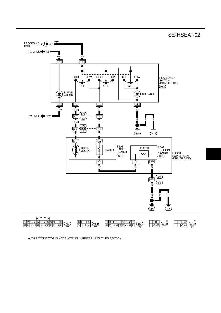
HEATED SEAT
SE-99
C
D
E
F
G
H
J
K
L
M
A
B
SE
Revision: 2006 July
2007 Murano
TIWB0198E