Nissan Murano Z50 (2007 year). Manual - part 69


  Index      Manuals     Nissan Murano Z50 (2007 year) - Service and Repair Manual


Search            copyright infringement  


Content      ..     67      68      69      70     ..


Nissan Murano Z50 (2007 year). Manual - part 69


ON BOARD DIAGNOSTIC (OBD) SYSTEM

EC-53

C

D

E

F

G

H

I

J

K

L

M

A

EC

Revision: 2006 July

2007 Murano

The SRT will indicate “CMPLT” at the time the respective self-diagnoses have one (1) OK result.

The emissions inspection requires “CMPLT” of the SRT only with OK self-diagnosis results.

When, during SRT driving pattern, 1st trip DTC (NG) is detected prior to “CMPLT” of SRT, the self-diagno-
sis memory must be erased from ECM after repair.

If the 1st trip DTC is erased, all the SRT will indicate “INCMP”.

NOTE:
SRT can be set as “CMPLT” together with the DTC(s). Therefore, DTC check must always be carried out
prior to the state emission inspection even though the SRT indicates “CMPLT”.

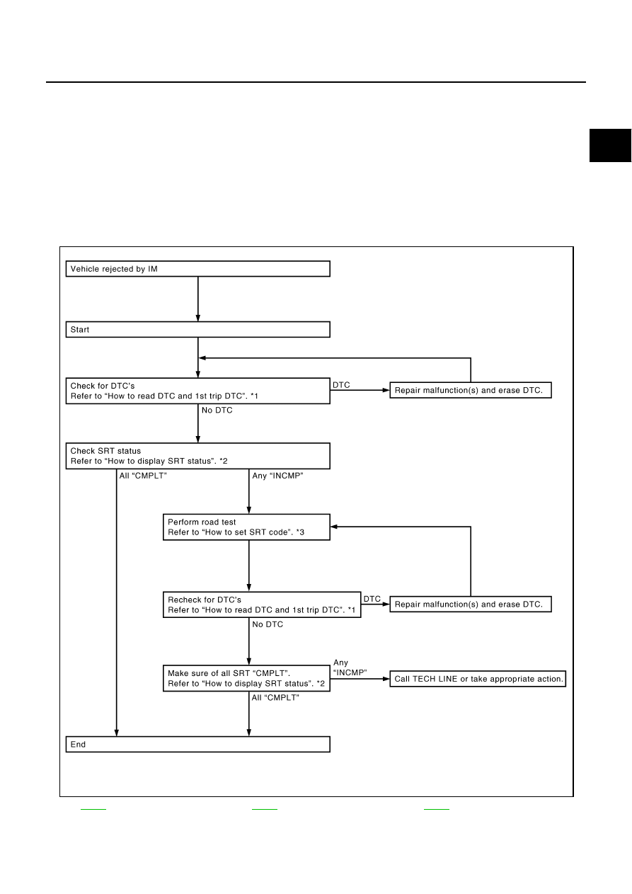
SRT Service Procedure

If a vehicle has failed the state emissions inspection due to one or more SRT items indicating “INCMP”, review
the flowchart diagnostic sequence on the next page.

*1

EC-50

*2

EC-54

*3

EC-54

PBIB2320E

EC-54

ON BOARD DIAGNOSTIC (OBD) SYSTEM

Revision: 2006 July

2007 Murano

How to Display SRT Status

 WITH CONSULT-II

Selecting “SRT STATUS” in “DTC CONFIRMATION” mode with
CONSULT-II.
For items whose SRT codes are set, a “CMPLT” is displayed on the
CONSULT-II screen; for items whose SRT codes are not set,
“INCMP” is displayed.
A sample of CONSULT-II display for SRT code is shown at right.
“INCMP” means the self-diagnosis is incomplete and SRT is not set.
“CMPLT” means the self-diagnosis is complete and SRT is set.
NOTE:
Though displayed on the CONSULT-II screen, “HO2S HTR” is not
SRT item.

 WITH GST

Selecting Service $01 with GST (Generic Scan Tool)

 NO TOOLS

A SRT code itself can not be displayed while only SRT status can be.

1.

Turn ignition switch ON and wait 20 seconds.

2.

SRT status is indicated as shown below.

When all SRT codes are set, MIL lights up continuously.

When any SRT codes are not set, MIL will flash periodically for 10 seconds.

How to Set SRT Code

To set all SRT codes, self-diagnosis for the items indicated above must be performed one or more times. Each
diagnosis may require a long period of actual driving under various conditions.

 WITH CONSULT-II

Perform corresponding DTC Confirmation Procedure one by one based on Performance Priority in the table
on 

EC-52

 .

 WITHOUT CONSULT-II

The most efficient driving pattern in which SRT codes can be properly set is explained on the next page. The
driving pattern should be performed one or more times to set all SRT codes.

SEF935Z

PBIB2317E

ON BOARD DIAGNOSTIC (OBD) SYSTEM

EC-55

C

D

E

F

G

H

I

J

K

L

M

A

EC

Revision: 2006 July

2007 Murano

Driving Pattern

PBIB2906E

EC-56

ON BOARD DIAGNOSTIC (OBD) SYSTEM

Revision: 2006 July

2007 Murano

The time required for each diagnosis varies with road surface conditions, weather, altitude, individual driv-
ing habits, etc.
Zone A refers to the range where the time, required for the diagnosis under normal conditions*, is the
shortest.
Zone B refers to the range where the diagnosis can still be performed if the diagnosis is not completed
within zone A.

*: Normal conditions refer to the following:

Sea level

Flat road

Ambient air temperature: 20 - 30

°

C (68 - 86

°

F)

Diagnosis is performed as quickly as possible under normal conditions.
Under different conditions [For example: ambient air temperature other than 20 - 30

°

C (68 - 86

°

F)], diag-

nosis may also be performed.

Pattern 1:

The engine is started at the engine coolant temperature of 

10 to 35

°

C (14 to 95

°

F)

(where the voltage between the ECM terminal 73 and ground is 3.0 - 4.3V).

The engine must be operated at idle speed until the engine coolant temperature is greater than
70

°

C (158

°

F) (where the voltage between the ECM terminal 73 and ground is lower than 1.4V).

The engine is started at the fuel tank temperature of warmer than 0

°

C (32

°

F) (where the voltage

between the ECM terminal 107 and ground is less than 4.1V).

Pattern 2:

When steady-state driving is performed again even after it is interrupted, each diagnosis can be con-
ducted. In this case, the time required for diagnosis may be extended.

Pattern 3:

Operate vehicle following the driving pattern shown in the figure.

Release the accelerator pedal during decelerating vehicle speed
from 90 km/h (56 MPH) to 0 km/h (0 MPH).

Pattern 4:

The accelerator pedal must be held very steady during steady-
state driving.

If the accelerator pedal is moved, the test must be conducted all
over again.

*1: Depress the accelerator pedal until vehicle speed is 90 km/h (56
MPH), then release the accelerator pedal and keep it released for
more than 10 seconds. Depress the accelerator pedal until vehicle
speed is 90 km/h (56 MPH) again.
*2: Checking the vehicle speed with GST is advised.

Suggested Transmission Gear Position
Set the shift lever in the D position.

TEST VALUE AND TEST LIMIT (GST ONLY — NOT APPLICABLE TO CONSULT-II)

The following is the information specified in Service $06 of SAE J1979.
The test value is a parameter used to determine whether a system/circuit diagnostic test is OK or NG while
being monitored by the ECM during self-diagnosis. The test limit is a reference value which is specified as the
maximum or minimum value and is compared with the test value being monitored.
These data (test value and test limit) are specified by Test ID (TID) and Component ID (CID) and can be dis-
played on the GST screen.

PBIB2244E

SRT item

Self-diagnostic test item

DTC

Test value (GST display)

Test limit

Unit

TID

CID

CATALYST

Three way catalyst function (Bank 1)

P0420

01H

01H

Max.

1/128

P0420

02H

81H

Min.

1

Three way catalyst function (Bank 2)

P0430

03H

02H

Max.

1/128

P0430

04H

82H

Min.

1

ON BOARD DIAGNOSTIC (OBD) SYSTEM

EC-57

C

D

E

F

G

H

I

J

K

L

M

A

EC

Revision: 2006 July

2007 Murano

EVAP

SYSTEM

EVAP control system (Small leak)

P0442

 05H

03H

Max.

1/128 mm

2

EVAP control system purge flow monitoring

P0441

06H

83H

Min.

20 mV

EVAP control system (Very small leak)

P0456

07H

03H

Max.

1/128 mm

2

HO2S

A/F sensor 1 (Bank 1)

P0131

41H

8EH

Min.

5 mV

P0132

42H

0EH

Max.

5 mV

P2A00

43H

0EH

Max.

0.002

P2A00

44H

8EH

Min. 0.002

P0133

45H

8EH

Min. 0.004

P0130

46H

0EH

Max.

5 mV

P0130

47H

8EH

Min. 5 

mV

P0133

48H

8EH

Min. 0.004

A/F sensor 1 (Bank 2)

P0151

4CH

8FH

Min.

5 mV

P0152

4DH

0FH

Max.

5 mV

P2A03

4EH

0FH

Max.

0.002

P2A03

4FH

8FH

Min.

0.002

P0153

50H

8FH

Min.

0.004

P0150

51H

0FH

Max.

5 mV

P0150

52H

8FH

Min.

5 mV

P0153

53H

8FH

Min.

0.004

Heated oxygen sensor 2 (Bank 1)

P0139

19H

86H

Min.

10mV/500 ms

P0137

1AH

86H

Min.

10 mV

P0138

1BH

06H

Max.

10 mV

P0138

1CH

06H

Max.

10 mV

Heated oxygen sensor 2 (Bank 2)

P0159

21H

87H

Min.

10mV/500 ms

P0157

22H

87H

Min.

10 mV

P0158

23H

07H

Max.

10 mV

P0158 24H

07H

Max.

10 

mV

HO2S HTR

A/F sensor 1 heater (Bank 1)

P0032

57H

10H

Max.

5 mV

P0031

58H

90H

Min.

5 mV

A/F sensor 1 heater (Bank 2)

P0052

59H

11H

Max.

5 mV

P0051

5AH

91H

Min.

5 mV

Heated oxygen sensor 2 heater (Bank 1)

P0038

2DH

0AH

Max.

20 mV

P0037

2EH

8AH

Min.

20 mV

Heated oxygen sensor 2 heater (Bank 2)

P0058

2FH

0BH

Max.

20 mV

P0057

30H

8BH

Min.

20 mV

SRT item

Self-diagnostic test item

DTC

Test value (GST display)

Test limit

Unit

TID

CID

EC-58

ON BOARD DIAGNOSTIC (OBD) SYSTEM

Revision: 2006 July

2007 Murano

HOW TO ERASE EMISSION-RELATED DIAGNOSTIC INFORMATION
How to Erase DTC

 WITH CONSULT-II

The emission related diagnostic information in the ECM can be erased by selecting “ERASE” in the “SELF-
DIAG RESULTS” mode with CONSULT-II.
If DTCs are displayed for both ECM and TCM (Transmission control module), they need to be erased individu-
ally from the ECM and TCM (Transmission control module).

NOTE:
If the DTC is not for CVT related items (see 

EC-8, "INDEX FOR DTC"

 ), skip steps 2 through 4.

1.

If the ignition switch stays ON after repair work, be sure to turn ignition switch OFF once. Wait at least 10
seconds and then turn it ON (engine stopped) again.

2.

Turn CONSULT-II ON and touch “TRANSMISSION”.

3.

Touch “SELF-DIAG RESULTS”.

4.

Touch “ERASE”. [The DTC in the TCM (Transmission control module) will be erased.] Then touch “BACK”
twice.

5.

Touch “ENGINE”.

6.

Touch “SELF-DIAG RESULTS”.

7.

Touch “ERASE”. (The DTC in the ECM will be erased.)

 WITH GST

The emission related diagnostic information in the ECM can be erased by selecting Service $04 with GST.

NOTE:
If the DTC is not for CVT related items (see 

EC-8, "INDEX FOR DTC"

 ), skip step 2.

1.

If the ignition switch stays ON after repair work, be sure to turn ignition switch OFF once. Wait at least 10
seconds and then turn it ON (engine stopped) again.

SCIA5442E

ON BOARD DIAGNOSTIC (OBD) SYSTEM

EC-59

C

D

E

F

G

H

I

J

K

L

M

A

EC

Revision: 2006 July

2007 Murano

2.

Perform 

CVT-31, "HOW TO ERASE DTC (WITH GST)"

 . (The DTC in TCM will be erased)

3.

Select Service $04 with GST (Generic Scan Tool).

 No Tools

NOTE:
If the DTC is not for CVT related items (see 

EC-8, "INDEX FOR DTC"

 ), skip step 2.

1.

If the ignition switch stays ON after repair work, be sure to turn ignition switch OFF once.
Wait at least 10 seconds and then turn it ON (engine stopped) again.

2.

Perform 

CVT-30, "HOW TO ERASE DTC"

 . (The DTC in the TCM will be erased.)

3.

Change the diagnostic test mode from Mode II to Mode I by depressing the accelerator pedal. Refer to

EC-60, "HOW TO SWITCH DIAGNOSTIC TEST MODE"

 .

If the battery is disconnected, the emission-related diagnostic information will be lost within 24
hours.

The following data are cleared when the ECM memory is erased.

Diagnostic trouble codes

1st trip diagnostic trouble codes

Freeze frame data

1st trip freeze frame data

System readiness test (SRT) codes

Test values

Actual work procedures are explained using a DTC as an example. Be careful so that not only the DTC, but all
of the data listed above, are cleared from the ECM memory during work procedures.

Malfunction Indicator Lamp (MIL)

NBS002Z4

DESCRIPTION

The MIL is located on the instrument panel.

1.

The MIL will light up when the ignition switch is turned ON with-
out the engine running. This is a bulb check.
If the MIL does not light up, refer to 

DI-37, "WARNING LAMPS"

 ,

or see 

EC-662

 .

2.

When the engine is started, the MIL should go off.
If the MIL remains on, the on board diagnostic system has
detected an engine system malfunction.

SEF217U

EC-60

ON BOARD DIAGNOSTIC (OBD) SYSTEM

Revision: 2006 July

2007 Murano

ON BOARD DIAGNOSTIC SYSTEM FUNCTION

The on board diagnostic system has the following three functions.

When there is an open circuit on MIL circuit, the ECM cannot warn the driver by lighting up MIL when there is
malfunction on engine control system.
Therefore, when electrical controlled throttle and part of ECM related diagnoses are continuously detected as
NG for 5 trips, ECM warns the driver that engine control system malfunctions and MIL circuit is open by means
of operating fail-safe function.
The fail-safe function also operates when above diagnoses except MIL circuit are detected and demands the
driver to repair the malfunction.

MIL Flashing Without DTC

When any SRT codes are not set, MIL may flash without DTC. For the details, refer to 

EC-54, "How to Display

SRT Status"

 .

HOW TO SWITCH DIAGNOSTIC TEST MODE

NOTE:

It is better to count the time accurately with a clock.

It is impossible to switch the diagnostic mode when an accelerator pedal position sensor circuit
has a malfunction.

Always ECM returns to Diagnostic Test Mode I after ignition switch is turned OFF.

How to Set Diagnostic Test Mode II (Self-diagnostic Results)

1.

Confirm that accelerator pedal is fully released, turn ignition switch ON and wait 3 seconds.

2.

Repeat the following procedure quickly 5 times within 5 seconds.

a.

Fully depress the accelerator pedal.

b.

Fully release the accelerator pedal.

3.

Wait 7 seconds, fully depress the accelerator pedal and keep it for approx. 10 seconds until the MIL starts
blinking.

Diagnostic Test 
Mode

KEY and ENG. 
Status

Function

Explanation of Function

Mode I

Ignition switch in 
ON position 

Engine stopped

BULB CHECK

This function checks the MIL bulb for damage (blown, 
open circuit, etc.).
If the MIL does not come on, check MIL circuit.

Engine running

MALFUNCTION
WARNING

This is a usual driving condition. When a malfunction is 
detected twice in two consecutive driving cycles (two trip 
detection logic), the MIL will light up to inform the driver 
that a malfunction has been detected.
The following malfunctions will light up or blink the MIL in 
the 1st trip.

Misfire (Possible three way catalyst damage)

One trip detection diagnoses

Mode II

Ignition switch in 
ON position 

Engine stopped

SELF-DIAGNOSTIC
RESULTS

This function allows DTCs and 1st trip DTCs to be read.

Engine operating condition in fail-safe mode

Engine speed will not rise more than 2,500 rpm due to the fuel cut

ON BOARD DIAGNOSTIC (OBD) SYSTEM

EC-61

C

D

E

F

G

H

I

J

K

L

M

A

EC

Revision: 2006 July

2007 Murano

NOTE:
Do not release the accelerator pedal for 10 seconds if MIL may start blinking on the halfway of this
10 seconds. This blinking is displaying SRT status and is continued for another 10 seconds. For
the details, refer to 

EC-54, "How to Display SRT Status"

 .

4.

Fully release the accelerator pedal.
ECM has entered to Diagnostic Test Mode II (Self-diagnostic results).

NOTE:
Wait until the same DTC (or 1st trip DTC) appears to confirm all DTCs certainly.

How to Erase Diagnostic Test Mode II (Self-diagnostic Results)

1.

Set ECM in Diagnostic Test Mode II (Self-diagnostic results). Refer to 

EC-60, "How to Set Diagnostic Test

Mode II (Self-diagnostic Results)"

 .

2.

Fully depress the accelerator pedal and keep it for more than 10 seconds.
The emission-related diagnostic information has been erased from the backup memory in the ECM.

3.

Fully release the accelerator pedal, and confirm the DTC 0000 is displayed.

DIAGNOSTIC TEST MODE I — BULB CHECK

In this mode, the MIL on the instrument panel should stay ON. If it remains OFF, check the bulb. Refer to 

DI-

37, "WARNING LAMPS"

   or see 

EC-662

 .

DIAGNOSTIC TEST MODE I — MALFUNCTION WARNING

This DTC number is clarified in Diagnostic Test Mode II (SELF-DIAGNOSTIC RESULTS)

PBIB0092E

MIL

Condition

ON

When the malfunction is detected.

OFF

No malfunction.

EC-62

ON BOARD DIAGNOSTIC (OBD) SYSTEM

Revision: 2006 July

2007 Murano

DIAGNOSTIC TEST MODE II — SELF-DIAGNOSTIC RESULTS

In this mode, the DTC and 1st trip DTC are indicated by the number of blinks of the MIL as shown below.
The DTC and 1st trip DTC are displayed at the same time. If the MIL does not illuminate in diagnostic test
mode I (Malfunction warning), all displayed items are 1st trip DTCs. If only one code is displayed when the MIL
illuminates in diagnostic test mode II (SELF-DIAGNOSTIC RESULTS), it is a DTC; if two or more codes are
displayed, they may be either DTCs or 1st trip DTCs. DTC No. is same as that of 1st trip DTC. These uniden-
tified codes can be identified by using the CONSULT-II or GST. A DTC will be used as an example for how to
read a code.

A particular trouble code can be identified by the number of four-digit numeral flashes. The “zero” is indicated
by the number of ten flashes. The “A” is indicated by the number of eleven flash. The length of time the
1,000th-digit numeral flashes on and off is 1.2 seconds consisting of an ON (0.6-second) - OFF (0.6-second)
cycle.
The 100th-digit numeral and lower digit numerals consist of a 0.3-second ON and 0.3-second OFF cycle.
A change from one digit numeral to another occurs at an interval of 1.0-second OFF. In other words, the later
numeral appears on the display 1.3 seconds after the former numeral has disappeared.
A change from one trouble code to another occurs at an interval of 1.8-second OFF.
In this way, all the detected malfunctions are classified by their DTC numbers. The DTC 0000 refers to no mal-
function. (See 

EC-8, "INDEX FOR DTC"

 )

How to Erase Diagnostic Test Mode II (Self-diagnostic Results)

The DTC can be erased from the back up memory in the ECM by depressing accelerator pedal. Refer to 

EC-

61, "How to Erase Diagnostic Test Mode II (Self-diagnostic Results)"

 .

If the battery is disconnected, the DTC will be lost from the backup memory within 24 hours.

Be careful not to erase the stored memory before starting trouble diagnoses.

PBIB3005E

ON BOARD DIAGNOSTIC (OBD) SYSTEM

EC-63

C

D

E

F

G

H

I

J

K

L

M

A

EC

Revision: 2006 July

2007 Murano

OBD System Operation Chart

NBS002Z5

RELATIONSHIP BETWEEN MIL, 1ST TRIP DTC, DTC, AND DETECTABLE ITEMS

When a malfunction is detected for the first time, the 1st trip DTC and the 1st trip freeze frame data are
stored in the ECM memory.

When the same malfunction is detected in two consecutive trips, the DTC and the freeze frame data are
stored in the ECM memory, and the MIL will come on. For details, refer to 

EC-45, "Two Trip Detection

Logic"

 .

The MIL will go off after the vehicle is driven 3 times (driving pattern B) with no malfunction. The drive is
counted only when the recorded driving pattern is met (as stored in the ECM). If another malfunction
occurs while counting, the counter will reset.

The DTC and the freeze frame data will be stored until the vehicle is driven 40 times (driving pattern A)
without the same malfunction recurring (except for Misfire and Fuel Injection System). For Misfire and
Fuel Injection System, the DTC and freeze frame data will be stored until the vehicle is driven 80 times
(driving pattern C) without the same malfunction recurring. The “TIME” in “SELF-DIAGNOSTIC
RESULTS” mode of CONSULT-II will count the number of times the vehicle is driven.

The 1st trip DTC is not displayed when the self-diagnosis results in OK for the 2nd trip.

SUMMARY CHART

For details about patterns B and C under “Fuel Injection System” and “Misfire”, see 

EC-65

 .

For details about patterns A and B under Other, see 

EC-67

 .

*1: Clear timing is at the moment OK is detected.
*2: Clear timing is when the same malfunction is detected in the 2nd trip.

Items

Fuel Injection System

Misfire

Other

MIL (goes off)

3 (pattern B)

3 (pattern B)

3 (pattern B)

DTC, Freeze Frame Data (no 
display)

80 (pattern C)

80 (pattern C)

40 (pattern A)

1st Trip DTC (clear)

1 (pattern C), *

1

1 (pattern C), *

1

1 (pattern B)

1st Trip Freeze Frame Data 
(clear)

*

1

 , *

2

*

1

 , *

2

1 (pattern B)

EC-64

ON BOARD DIAGNOSTIC (OBD) SYSTEM

Revision: 2006 July

2007 Murano

RELATIONSHIP BETWEEN MIL, DTC, 1ST TRIP DTC AND DRIVING PATTERNS FOR “MISFIRE 
” <EXHAUST QUALITY DETERIORATION>, “FUEL INJECTION SYSTEM”

*1: When the same malfunction is 

detected in two consecutive trips, 
MIL will light up.

*2: MIL will go off after vehicle is driven 

3 times (pattern B) without any mal-
functions.

*3: When the same malfunction is 

detected in two consecutive trips, the 
DTC and the freeze frame data will 
be stored in ECM.

*4: The DTC and the freeze frame data 

will not be displayed any longer after 
vehicle is driven 80 times (pattern C) 
without the same malfunction. (The 
DTC and the freeze frame data still 
remain in ECM.)

*5: When a malfunction is detected for 

the first time, the 1st trip DTC and 
the 1st trip freeze frame data will be 
stored in ECM.

*6: The 1st trip DTC and the 1st trip 

freeze frame data will be cleared at 
the moment OK is detected.

*7: When the same malfunction is 

detected in the 2nd trip, the 1st trip 
freeze frame data will be cleared.

*8: 1st trip DTC will be cleared when 

vehicle is driven once (pattern C) 
without the same malfunction after 
DTC is stored in ECM.

SEF392S

ON BOARD DIAGNOSTIC (OBD) SYSTEM

EC-65

C

D

E

F

G

H

I

J

K

L

M

A

EC

Revision: 2006 July

2007 Murano

EXPLANATION FOR DRIVING PATTERNS FOR “MISFIRE <EXHAUST QUALITY DETERIORA-
TION>”, “FUEL INJECTION SYSTEM”
<Driving Pattern B>

Driving pattern B means the vehicle operation as follows:
All components and systems should be monitored at least once by the OBD system.

The B counter will be cleared when the malfunction is detected once regardless of the driving pattern.

The B counter will be counted up when driving pattern B is satisfied without any malfunction.

The MIL will go off when the B counter reaches 3. (*2 in “OBD SYSTEM OPERATION CHART”)

<Driving Pattern C>

Driving pattern C means the vehicle operation as follows:
The following conditions should be satisfied at the same time:
Engine speed: (Engine speed in the freeze frame data) 

±

375 rpm

Calculated load value: (Calculated load value in the freeze frame data) x (1

±

0.1) [%]

Engine coolant temperature (T) condition:

When the freeze frame data shows lower than 70

°

C (158

°

F), T should be lower than 70

°

C (158

°

F).

When the freeze frame data shows higher than or equal to 70

°

C (158

°

F), T should be higher than or equal

to 70

°

C (158

°

F).

Example:
If the stored freeze frame data is as follows:
Engine speed: 850 rpm, Calculated load value: 30%, Engine coolant temperature: 80

°

C (176

°

F)

To be satisfied with driving pattern C, the vehicle should run under the following conditions:
Engine speed: 475 - 1,225 rpm, Calculated load value: 27 - 33%, Engine coolant temperature: more than 70

°

C

(158

°

F)

The C counter will be cleared when the malfunction is detected regardless of vehicle conditions above.

The C counter will be counted up when vehicle conditions above is satisfied without the same malfunction.

The DTC will not be displayed after C counter reaches 80 (*2 in OBD SYSTEM OPERATION CHART).

The 1st trip DTC will be cleared when C counter is counted once without the same malfunction after DTC
is stored in ECM.

EC-66

ON BOARD DIAGNOSTIC (OBD) SYSTEM

Revision: 2006 July

2007 Murano

RELATIONSHIP BETWEEN MIL, DTC, 1ST TRIP DTC AND DRIVING PATTERNS EXCEPT   FOR 
“MISFIRE <EXHAUST QUALITY DETERIORATION>”, “FUEL INJECTION SYSTEM”

*1: When the same malfunction is 

detected in two consecutive trips, 
MIL will light up.

*2: MIL will go off after vehicle is driven 

3 times (pattern B) without any mal-
functions.

*3: When the same malfunction is 

detected in two consecutive trips, the 
DTC and the freeze frame data will 
be stored in ECM.

*4: The DTC and the freeze frame data 

will not be displayed any longer after 
vehicle is driven 40 times (pattern A) 
without the same malfunction.
(The DTC and the freeze frame data 
still remain in ECM.)

*5: When a malfunction is detected for 

the first time, the 1st trip DTC and 
the 1st trip freeze frame data will be 
stored in ECM.

*6: 1st trip DTC will be cleared after 

vehicle is driven once (pattern B) 
without the same malfunction.

*7: When the same malfunction is 

detected in the 2nd trip, the 1st trip 
freeze frame data will be cleared.

SEF393SD

ON BOARD DIAGNOSTIC (OBD) SYSTEM

EC-67

C

D

E

F

G

H

I

J

K

L

M

A

EC

Revision: 2006 July

2007 Murano

EXPLANATION FOR DRIVING PATTERNS EXCEPT   FOR “MISFIRE <EXHAUST QUALITY 
DETERIORATION>”, “FUEL INJECTION SYSTEM”
<Driving Pattern A>

The A counter will be cleared when the malfunction is detected regardless of (1) - (4).

The A counter will be counted up when (1) - (4) are satisfied without the same malfunction.

The DTC will not be displayed after the A counter reaches 40 (*2 in OBD SYSTEM OPERATION CHART).

<Driving Pattern B>

Driving pattern B means the vehicle operation as follows:
All components and systems should be monitored at least once by the OBD system.

The B counter will be cleared when the malfunction is detected once regardless of the driving pattern.

The B counter will be counted up when driving pattern B is satisfied without any malfunctions.

The MIL will go off when the B counter reaches 3 (*2 in OBD SYSTEM OPERATION CHART).

AEC574

EC-68

BASIC SERVICE PROCEDURE

Revision: 2006 July

2007 Murano

BASIC SERVICE PROCEDURE

PFP:00018

Basic Inspection

NBS002Z6

1. 

INSPECTION START

1.

Check service records for any recent repairs that may indicate a related malfunction, or a current need for
scheduled maintenance.

2.

Open engine hood and check the following:

Harness connectors for improper connections

Wiring harness for improper connections, pinches and cut

Vacuum hoses for splits, kinks and improper connections

Hoses and ducts for leaks

Air cleaner clogging

Gasket

3.

Confirm that electrical or mechanical loads are not applied.

Headlamp switch is OFF.

Air conditioner switch is OFF.

Rear window defogger switch is OFF.

Steering wheel is in the straight-ahead position, etc.

4.

Start engine and warm it up until engine coolant temperature
indicator points the middle of gauge.
Ensure engine stays below 1,000 rpm.

5.

Run engine at about 2,000 rpm for about 2 minutes under no-
load.

6.

Make sure that no DTC is displayed with CONSULT-II or GST.

OK or NG

OK

>> GO TO 3.

NG

>> GO TO 2.

2. 

REPAIR OR REPLACE

Repair or replace components as necessary according to corresponding Diagnostic Procedure.

>> GO TO 3.

SEF983U

SEF976U

SEF977U


Content      ..     67      68      69      70     ..