Nissan Murano Z50 (2007 year). Manual - part 67
ENGINE CONTROL SYSTEM
EC-21
C
D
E
F
G
H
I
J
K
L
M
A
EC
Revision: 2006 July
2007 Murano
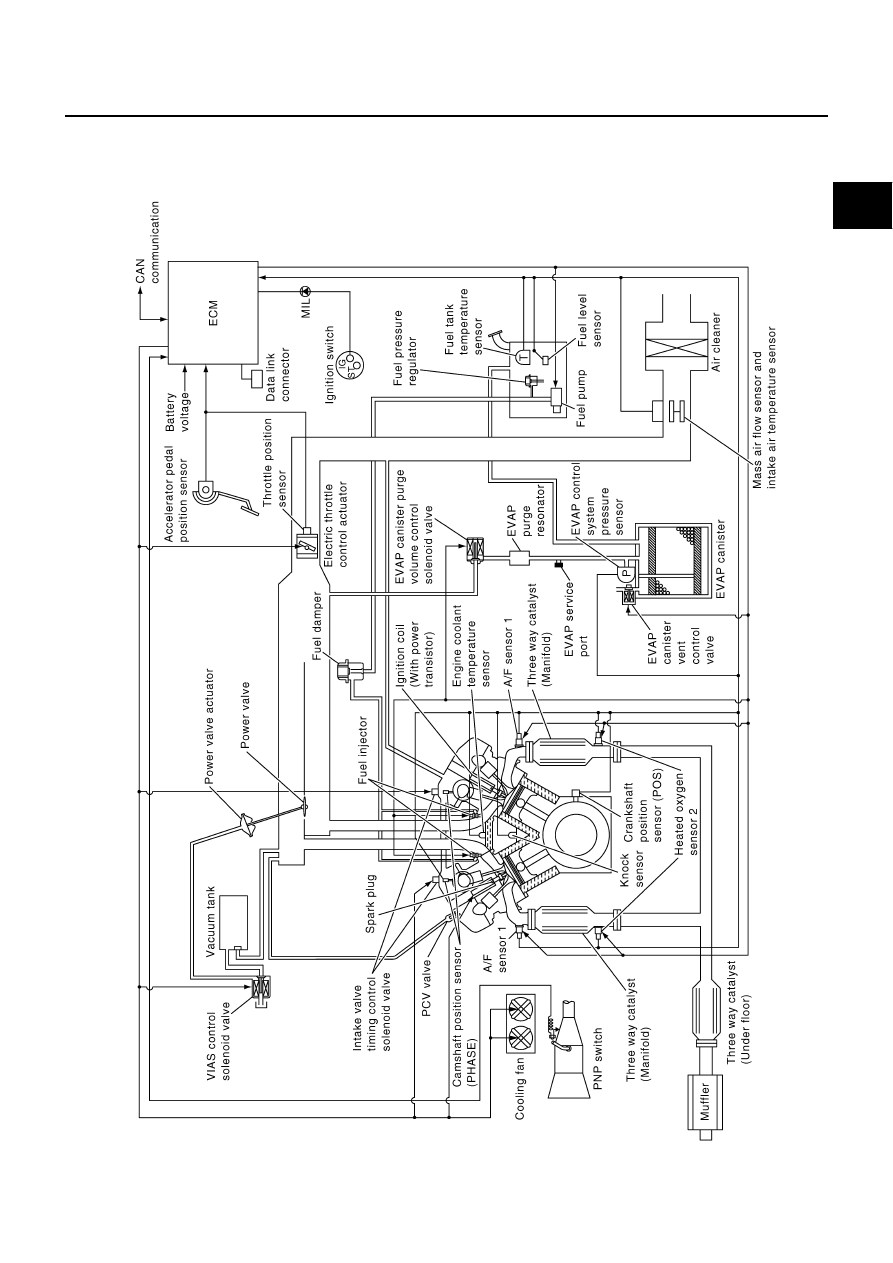
ENGINE CONTROL SYSTEM
PFP:23710
System Diagram
NBS002YI
PBIB2307E
|
|
|
ENGINE CONTROL SYSTEM EC-21 C D E F G H I J K L M A EC Revision: 2006 July 2007 Murano ENGINE CONTROL SYSTEM PFP:23710 System Diagram NBS002YI PBIB2307E |