Nissan Murano Z50 (2007 year). Manual - part 35
BODY REPAIR
BL-305
C
D
E
F
G
H
J
K
L
M
A
B
BL
Revision: 2006 July
2007 Murano
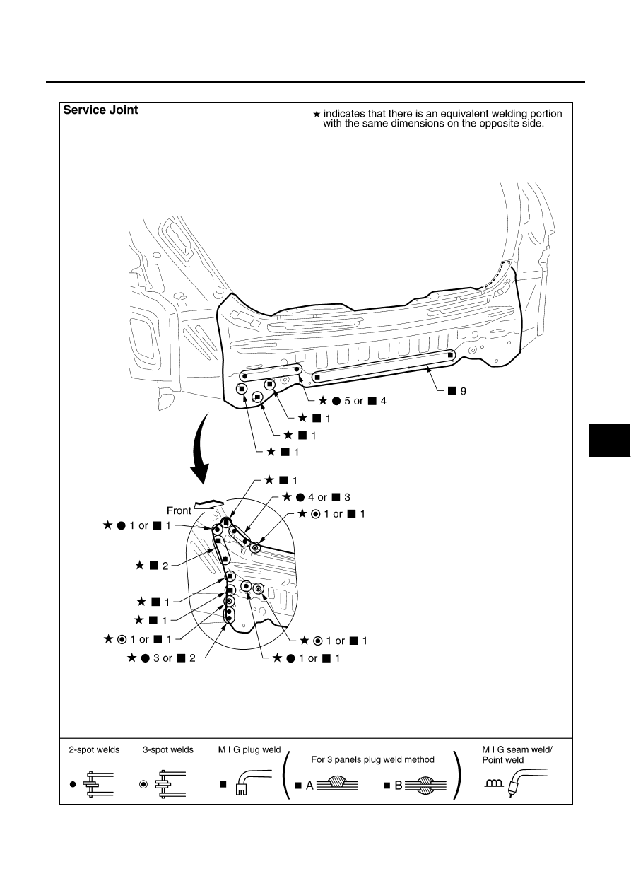
REAR PANEL
Change parts
●
Rear panel assembly
SIIA2192E
|
|
|
BODY REPAIR BL-305 C D E F G H J K L M A B BL Revision: 2006 July 2007 Murano REAR PANEL Change parts ● Rear panel assembly SIIA2192E |