Nissan Murano Z50 (2007 year). Manual - part 18
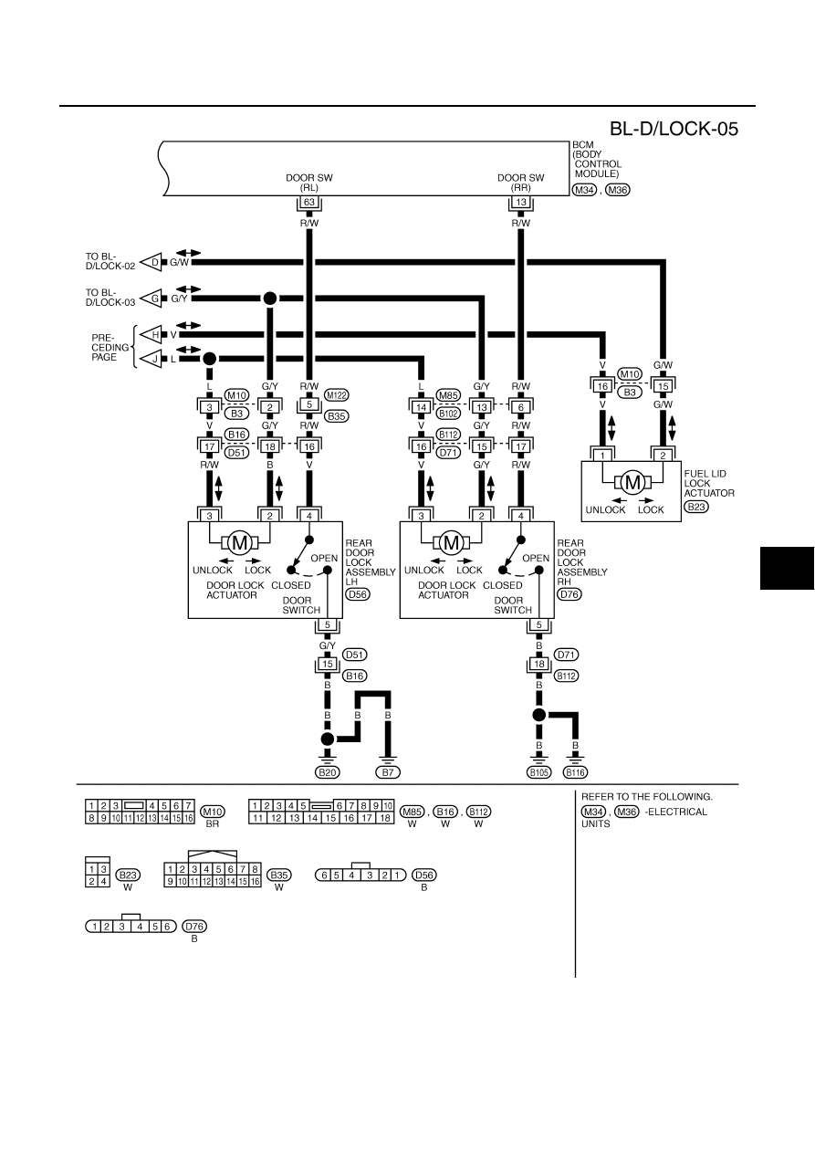
POWER DOOR LOCK SYSTEM
BL-33
C
D
E
F
G
H
J
K
L
M
A
B
BL
Revision: 2006 July
2007 Murano
TIWB0770E
|
|
|
POWER DOOR LOCK SYSTEM BL-33 C D E F G H J K L M A B BL Revision: 2006 July 2007 Murano TIWB0770E |