Nissan Murano Z50 (2006 year). Manual - part 187
REAR FINAL DRIVE ASSEMBLY
RFD-29
C
E
F
G
H
I
J
K
L
M
A
B
RFD
Revision: 2006 August
2006 Murano
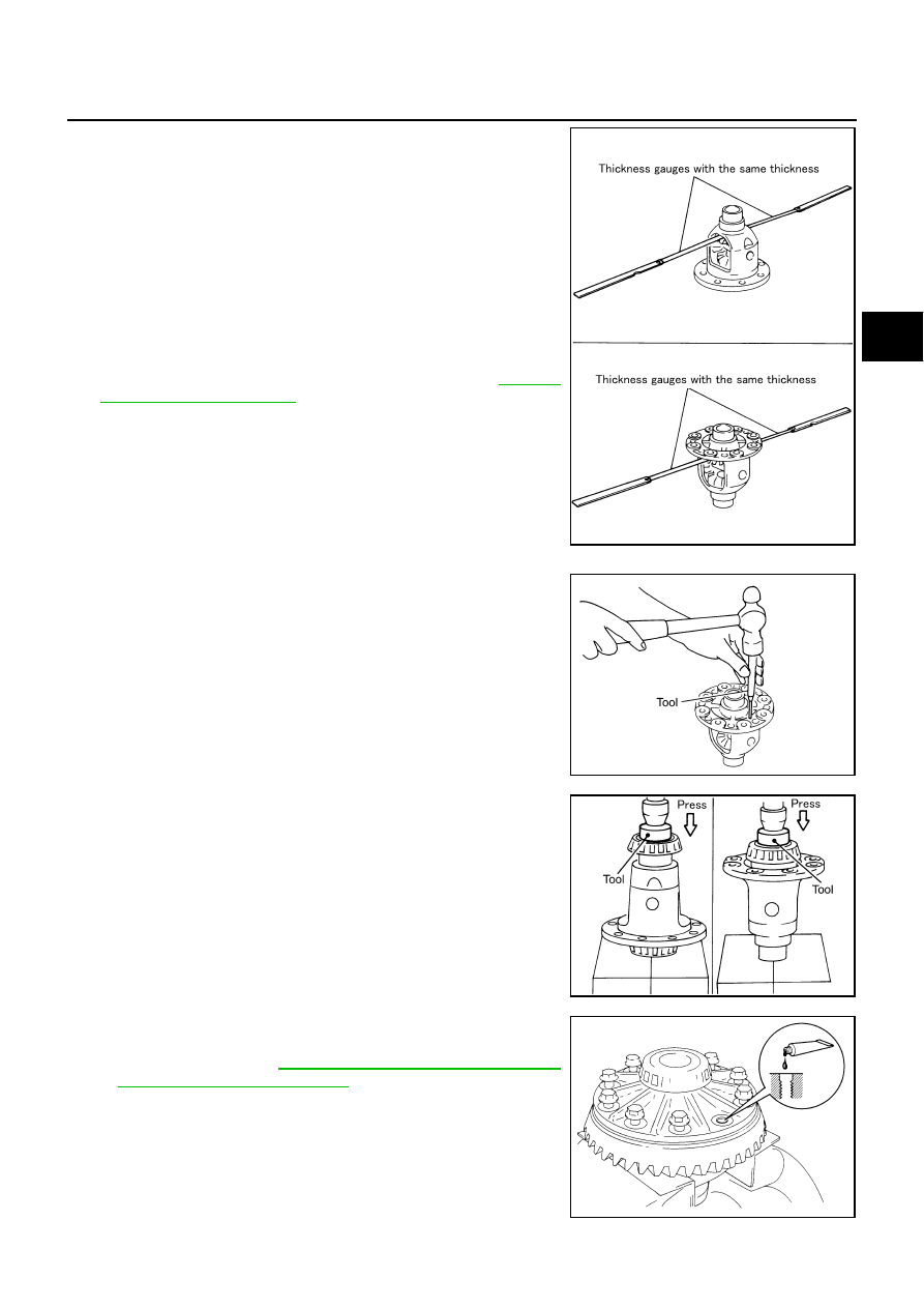
b.
Using thickness gauges, measure the clearance between side
gear back and differential case at 3 different positions, while
rotating side gear. Average the 3 readings, and then measure
the clearance. (Measure the clearance of the other side as well.)
CAUTION:
To prevent side gear from tilting, insert thickness gauges
with the same thickness from both sides.
c.
If the back clearance is outside the specification, use a thicker/
thinner side gear thrust washer to adjust. Refer to
.
CAUTION:
Select a side gear thrust washer for right and left individu-
ally.
6.
Drive a lock pin into pinion mating shaft, using the pin punch.
CAUTION:
Do not reuse lock pin.
7.
Press side bearing inner races to differential case, using the
drift.
CAUTION:
Do not reuse side bearing inner race.
8.
Apply thread locking sealant into the thread hole of drive gear.
●
Use Genuine Medium Strength Thread Locking Sealant or
equivalent. Refer to
CAUTION:
The drive gear back and threaded holes shall be cleaned
and decreased sufficiently.
Side gear back clearance specification:
0.2 mm (0.008 in) or less.
(Each gear should rotate smoothly without excessive
resistance during differential motion.)
When the back clearance is large:
Use a thicker thrust washer.
When the back clearance is small:
Use a thinner thrust washer.
Tool number
: ST23550000 (
—
)
SDIA0583E
PDIA0062E
Tool number
: KV40105020 (
—
)
PDIA0052E
SPD554