Nissan Murano Z50 (2006 year). Manual - part 91
DTC P0130, P0150 A/F SENSOR 1
EC-235
C
D
E
F
G
H
I
J
K
L
M
A
EC
Revision: 2006 August
2006 Murano
Specification data are reference values and are measured between each terminal and ground.
Pulse signal is measured by CONSULT-II.
CAUTION:
Do not use ECM ground terminals when measuring input/output voltage. Doing so may result in dam-
age to the ECM's transistor. Use a ground other than ECM terminals, such as the ground.
: Average voltage for pulse signal (Actual pulse signal can be confirmed by oscilloscope.)
Diagnostic Procedure
NBS003AA
1.
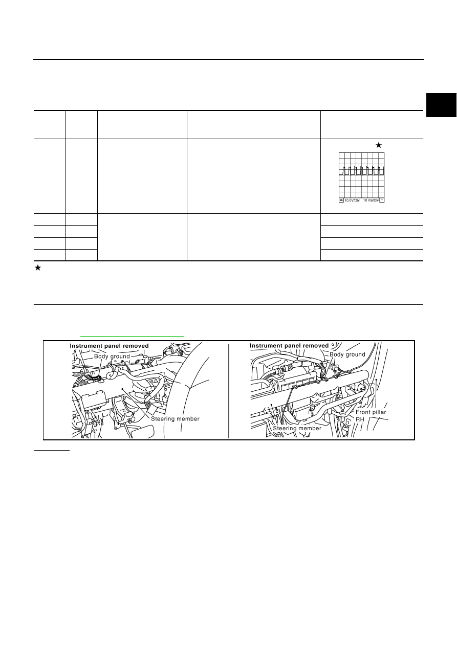
CHECK GROUND CONNECTIONS
1.
Turn ignition switch OFF.
2.
Loosen and retighten two ground screws on the body.
Refer to
OK or NG
OK
>> GO TO 2.
NG
>> Repair or replace ground connections.
TERMI-
NAL
NO.
WIRE
COLOR
ITEM
CONDITION
DATA (DC Voltage)
24
V
A/F sensor 1 heater
(Bank 2)
[Engine is running]
●
Warm-up condition
●
Idle speed
Approximately 5V
57
P
A/F sensor 1 (Bank 2)
[Engine is running]
●
Warm-up condition
●
Idle speed
Approximately 2.6V
58
SB
Approximately 2.3V
76
G/Y
Approximately 3.1V
77
LG
Approximately 2.3V
PBIB1584E
PBIB1835E