Nissan Murano Z50 (2006 year). Manual - part 85
TROUBLE DIAGNOSIS - SPECIFICATION VALUE
EC-139
C
D
E
F
G
H
I
J
K
L
M
A
EC
Revision: 2006 August
2006 Murano
20.
CHECK “A/F ALPHA-B1”, “A/F ALPHA-B2”, AND “B/FUEL SCHDL”
Select “A/F ALPHA-B1”, “A/F ALPHA-B2”, and “B/FUEL SCHDL” in “DATA MONITOR (SPEC)” mode, and
make sure that the each indication is within the SP value.
OK or NG
OK
>> INSPECTION END
NG (“B/FUEL SCHDL” is more, “A/F ALPHA-B1”, “A/F ALPHA-B2” are less than the SP value)>>GO TO 21.
21.
DISCONNECT AND RECONNECT MASS AIR FLOW SENSOR HARNESS CONNECTOR
1.
Stop the engine.
2.
Disconnect mass air flow sensor harness connector. Check pin terminal and connector for damage and
then reconnect it again.
>> GO TO 22.
22.
CHECK “A/F ALPHA-B1”, “A/F ALPHA-B2”
1.
Start engine.
2.
Select “A/F ALPHA-B1”, “A/F ALPHA-B2” in “DATA MONITOR (SPEC)” mode, and make sure that the
each indication is within the SP value.
OK or NG
OK
>> 1. Detect malfunctioning part of mass air flow sensor circuit and repair it. Refer to
2. GO TO 29.
NG
>> GO TO 23.
23.
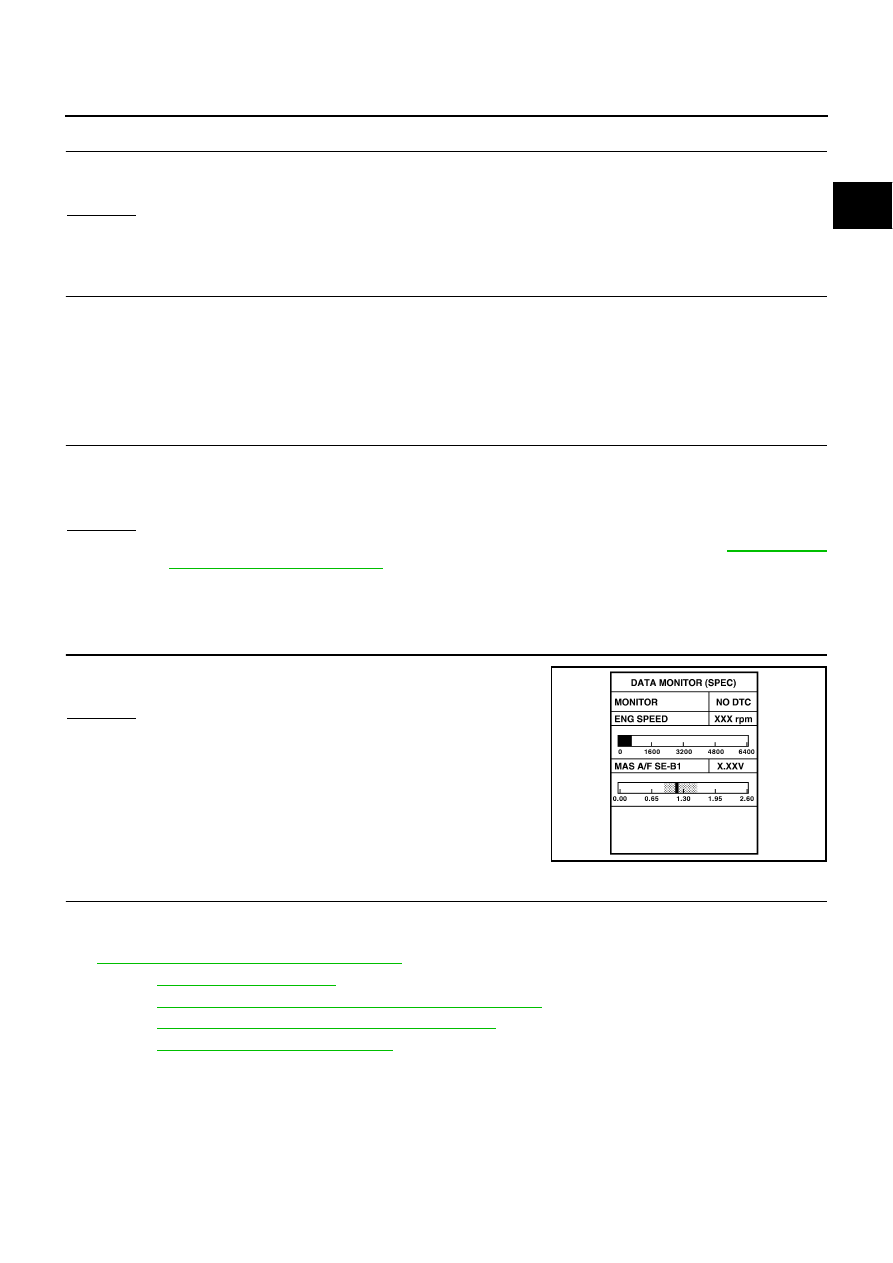
CHECK “MAS A/F SE-B1”
Select “MAS A/F SE-B1” in “DATA MONITOR (SPEC)” mode, and
make sure that the indication is within the SP value.
OK or NG
OK
>> GO TO 24.
NG (More than the SP value)>>Replace mass air flow sensor, and
then GO TO 29.
24.
REPLACE ECM
1.
Replace ECM.
2.
Perform initialization of NVIS(NATS) system and registration of all NVIS(NATS) ignition key IDs. Refer to
BL-238, "ECM Re-communicating Function"
.
3.
Perform
.
4.
Perform
EC-75, "Accelerator Pedal Released Position Learning"
5.
Perform
EC-76, "Throttle Valve Closed Position Learning"
6.
Perform
EC-76, "Idle Air Volume Learning"
>> GO TO 29.
PBIB2370E