Nissan Murano Z50 (2005 year). Manual - part 204


  Index      Manuals     Nissan Murano Z50 (2005 year) - Service and Repair Manual


Search            copyright infringement  


Content      ..     202      203      204      205     ..


Nissan Murano Z50 (2005 year). Manual - part 204


SUNROOF

RF-45

C

D

E

F

G

H

J

K

L

M

A

B

RF

Revision: 2005 August

2005 Murano

CAUTION:

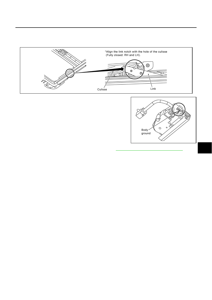
Before installing the sunroof motor assembly, be sure to place the link and wire assembly in the
symmetrical and fully closed position.

Align the link notch with the hole of the culisse (fully closed : RH and LH).

2.

Confirm the body ground of the noise cover is connected.

3.

Initialization it after installing the sunroof motor. Refer to 

RF-12, "INITIALIZATION PROCEDURE"

 .

PIIA5062E

PIIA5063E

RF-46

SUNROOF

Revision: 2005 August

2005 Murano

RFD-1

REAR FINAL DRIVE

D  DRIVELINE/AXLE

CONTENTS

C

E

F

G

H

I

J

K

L

M

SECTION 

RFD

A

B

RFD

Revision: 2005 August

2005 Murano

REAR FINAL DRIVE

PRECAUTIONS .......................................................... 2

Service Notice or Precautions  .................................. 2

PREPARATION ........................................................... 3

Special Service Tools  ............................................... 3
Commercial Service Tools ........................................ 5

NOISE, VIBRATION AND HARSHNESS (NVH) 
TROUBLESHOOTING ................................................ 6

NVH Troubleshooting Chart  ..................................... 6

DESCRIPTION ............................................................ 7

Cross-Sectional View  ............................................... 7

DIFFERENTIAL GEAR OIL  ........................................ 8

Changing Differential Gear Oil  ................................. 8

DRAINING ............................................................. 8
FILLING ................................................................. 8

Checking Differential Gear Oil .................................. 8

OIL LEAKAGE AND OIL LEVEL  ........................... 8

FRONT OIL SEAL  ...................................................... 9

Removal and Installation  .......................................... 9

REMOVAL ............................................................. 9
INSTALLATION ..................................................... 9

SIDE OIL SEAL  .........................................................11

Removal and Installation  .........................................11

REMOVAL ............................................................11
INSTALLATION ....................................................11

ELECTRIC CONTROLLED COUPLING ................... 12

Removal and Installation  ........................................ 12

REMOVAL ........................................................... 12
INSTALLATION ................................................... 13

REAR FINAL DRIVE ASSEMBLY  ............................ 14

Removal and Installation  ........................................ 14

COMPONENTS ................................................... 14
REMOVAL ........................................................... 14
INSTALLATION ................................................... 15

Disassembly and Assembly .................................... 16

COMPONENTS ................................................... 16
ASSEMBLY INSPECTION AND ADJUSTMENT ... 17
DISASSEMBLY ................................................... 21
INSPECTION AFTER DISASSEMBLY ................ 24
ASSEMBLY ......................................................... 25

SERVICE DATA AND SPECIFICATIONS (SDS)  ...... 34

General Specifications ............................................ 34
Inspection and Adjustment  ..................................... 34

DRIVE GEAR RUNOUT  ...................................... 34
DIFFERENTIAL SIDE GEAR CLEARANCE  ....... 34
PRELOAD TORQUE  ........................................... 34
BACKLASH ......................................................... 34
COMPANION FLANGE RUNOUT ....................... 34
SELECTIVE PARTS  ............................................ 34

RFD-2

PRECAUTIONS

Revision: 2005 August

2005 Murano

PRECAUTIONS

PFP:00001

Service Notice or Precautions

ADS001BB

Check for the correct installation status prior to removal or disassembly. If matching marks are required,
be certain they do not interfere with the function of the parts when applied.

Overhaul should be done in a clean work area, it is preferable to work in dustproof area.

Before disassembly, using steam or white gasoline, completely remove sand and mud from the exterior of
the unit, preventing them from entering into the unit during disassembly or assembly.

Check appearance of the disassembled parts for damage, deformation, and unusual wear. Replace them
with a new ones if necessary.

Gaskets, seals and O-rings should be replaced any time when the unit is disassembled.

In principle, tighten bolts or nuts gradually in several steps working diagonally from inside to outside. If
tightening sequence is specified, observe it.

Clean and flush the parts sufficiently and blow-dry them.

Be careful not to damage sliding surfaces and mating surfaces.

When applying sealant, remove the old sealant from the mounting surface; then remove any moisture, oil,
and foreign materials from the application and mounting surfaces.

Always use shop paper for cleaning the inside of components.

Avoid using cotton gloves or shop rags to prevent entering of lint.

During assembly, observe the specified tightening torque, and apply new differential oil, petroleum jelly, or
multi-purpose grease as specified for each vehicle, if necessary.

PREPARATION

RFD-3

C

E

F

G

H

I

J

K

L

M

A

B

RFD

Revision: 2005 August

2005 Murano

PREPARATION

PFP:00002

Special Service Tools

ADS001BC

The actual shapes of Kent-Moore tools may differ from those of special service tools illustrated here.

Tool number
(Kent-Moore No.)
Tool name

Description

ST27861000
(

)

Drift
a: 62 mm (2.44 in) dia.
b: 52 mm (2.05 in) dia.

Installing final drive front oil seal

KV38100200
(J-26233)
Drift
a: 65 mm (2.56 in) dia.
b: 49 mm (1.93 in) dia.

Installing final drive front oil seal

Installing final drive side oil seal

ST3127S000
(J-25765-A)
Preload gauge

Measuring preload torque

ST33052000
(

)

Drift
a: 22 mm (0.87 in) dia.
b: 28 mm (1.10 in) dia.

Removing side bearing inner race

KV40100610
(J-26089)
Drift
a: 63 mm (2.48 in) dia.
b: 54.3 mm (2.138 in) dia.

Removing and installing gear carrier and 
rear cover (2 pieces are used)

Installing pinion front bearing inner race

ST23550000
(

)

Pin punch
a: 4.5 mm (0.177 in) dia.

Removing and installing lock pin

ST17130000
(

)

Drift 
a: 31.8 mm (1.252 in) dia.
b: 58 mm (2.28 in) dia.

Installing pinion rear bearing outer race

ZZA0832D

ZZA1143D

ZZA0503D

ZZA1023D

ZZA1000D

NT410

ZZA0836D

RFD-4

PREPARATION

Revision: 2005 August

2005 Murano

ST33230000
(J-25805-01)
Drift
a: 51 mm (2.01 in) dia.
b: 41 mm (1.61 in) dia.
c: 28.5 mm (1.122 in) dia.

Installing pinion front bearing outer race

ST23860000
(

)

Drift
a: 38 mm (1.50 in) dia.
b: 33 mm (1.30 in) dia.

Installing pinion rear bearing inner race

Installing pinion front bearing inner race

ST38220000
(

)

Press stand
a: 63 mm (2.48 in) dia.
b: 65 mm (2.56 in)

Installing pinion front bearing inner race

KV40105020
(

)

Drift
a: 39.7 mm (1.563 in) dia.
b: 35 mm (1.38 in) dia.
c: 15 mm (0.59 in)

Installing side bearing inner race

ST35271000
(J-26091)
Drift
a: 72 mm (2.83 in) dia.
b: 63 mm (2.48 in) dia.

Installing center oil seal

ST22350000
(J-25678-01)
Drift
a: 34 mm (1.34 in) dia.
b: 28 mm (1.10 in) dia.
c: 390 mm (15.35 in)

Installing coupling front bearing

Tool number
(Kent-Moore No.)
Tool name

Description

ZZA1046D

ZZA0534D

ZZA1058D

ZZA1133D

ZZA0814D

ZZA0546D

PREPARATION

RFD-5

C

E

F

G

H

I

J

K

L

M

A

B

RFD

Revision: 2005 August

2005 Murano

Commercial Service Tools

ADS001BD

KV381086S1
(

)

Dummy cover set

1. KV38108610

(

)

Dummy cover

2. KV38108621

(

)

Dummy cover spacer

3. KV38108630

(

)

Dummy cover shim

Checking backlash

Checking drive gear runout

Checking tooth contact

KV38108500
(

)

Drive pinion socket

Measuring preload torque

Removing and installing drive pinion nut

KV38108400
(

)

Pinion nut wrench

Measuring preload torque

Removing drive pinion nut

Tool number
(Kent-Moore No.)
Tool name

Description

SDIA2313E

ZZA1205D

ZZA1206D

Tool name

Description

Flange wrench

Removing and installing companion flange 
lock nut

Power tool

Loosening nuts and bolts

NT771

PBIC0190E

RFD-6

NOISE, VIBRATION AND HARSHNESS (NVH) TROUBLESHOOTING

Revision: 2005 August

2005 Murano

NOISE, VIBRATION AND HARSHNESS (NVH) TROUBLESHOOTING

PFP:00003

NVH Troubleshooting Chart

ADS001BE

Use the chart below to help you find the cause of the symptom. If necessary, repair or replace these parts.

×

: Applicable

Reference page

R

e

fe

r to


RFD-2

4

, "

INSPECTION A

FTER DISASSEM

BL

Y

"

 .

R

e

fe

r to


RFD-1

8

, "

T

oot

h C

ont

act

"

 .

R

e

fe

r to


RFD-2

4

, "

INSPECTION A

FTER DISASSEM

BL

Y

"

 .

R

e

fe

r to


RFD-2

0

, "

B

a

ckl

as

h

"

 .

R

e

fe

r to


RFD-2

0

, "

C

o

m

pani

on Fl

ange

 R

u

n

out

"

 .

R

e

fe

r to


RFD-8

, "

Ch

e

c

k

in

g

 Dif

fe

re

n

tia

l Ge

a

Oil

"

 .

NV

H

 in

 PR 

s

e

c

ti

o

n

.

NV

H

 in

 F

AX, 

RAX, FSU 

a

n

d

 RSU 

s

e

c

ti

o

n

s

.

NV

H

 in

 W

T

 s

e

c

tio

n

.

NV

H

 in

 W

T

 s

e

c

tio

n

.

N

V

H

 i

n

 F

AX and R

AX sec

ti

on.

NV

H

 in

 BR 

s

e

c

ti

o

n

.

NV

H

 in

 PS 

s

e

c

ti

o

n

.

Possible cause and SUSPECTED PARTS

G

e

ar

 t

oot

h r

o

u

g

h

G

e

ar

 con

ta

c

im

pr

o

per

T

oot

h sur

fa

c

es w

o

rn

B

a

ckl

as

h i

n

c

o

rr

ect

C

o

m

pani

on f

lan

ge exc

e

ssi

ve

 r

unou

t

G

e

ar

 oi

im

pr

o

per

P

R

OPE

LLER SHAFT

A

X

LE AND 

SUSPENSION

TI

R

E

S

ROAD W

H

EEL

DRIVE SHAFT

BR

AK

E

S

S

T

EERI

N

G

Symptom

Noise

×

×

×

×

×

×

×

×

×

×

×

×

×

DESCRIPTION

RFD-7

C

E

F

G

H

I

J

K

L

M

A

B

RFD

Revision: 2005 August

2005 Murano

DESCRIPTION

PFP:00000

Cross-Sectional View

ADS001BF

SDIA0141E

RFD-8

DIFFERENTIAL GEAR OIL

Revision: 2005 August

2005 Murano

DIFFERENTIAL GEAR OIL

PFP:KLD30

Changing Differential Gear Oil

ADS001BG

DRAINING

1.

Stop engine.

2.

Remove drain plug and drain oil.

3.

Set a gasket on drain plug and install it to final drive assembly
and tighten to the specified torque. Refer to 

RFD-16, "COMPO-

NENTS"

 . 

CAUTION:

Do not reuse gasket.

FILLING

1.

Remove filler plug. Fill with new oil until oil level reaches the
specified level near filler plug mounting hole.

2.

After refilling oil, check oil level. Set a gasket to filler plug, then
install it to final drive assembly. Refer to 

RFD-16, "COMPO-

NENTS"

 .

CAUTION:

Do not reuse gasket.

Checking Differential Gear Oil

ADS001BH

OIL LEAKAGE AND OIL LEVEL

Make sure that oil is not leaking from final drive assembly or around it.

Check oil level from filler plug mounting hole as shown in the fig-
ure.

CAUTION:

Do not start engine while checking oil level.

Set a gasket on filler plug and install it on final drive assembly.
Refer to 

RFD-16, "COMPONENTS"

 . 

CAUTION:

Do not reuse gasket.

PDIA0454E

Oil grade and Viscosity:

Refer to 

MA-10, "Fluids and Lubricants"

 .

Oil capacity:

Approx. 0.55  (1-1/8 US pt, 1 Imp pt)

PDIA0453E

PDIA0453E

FRONT OIL SEAL

RFD-9

C

E

F

G

H

I

J

K

L

M

A

B

RFD

Revision: 2005 August

2005 Murano

FRONT OIL SEAL

PFP:38189

Removal and Installation

ADS001BI

REMOVAL

1.

Remove propeller shaft. Refer to 

PR-5, "Removal and Installation"

 .

2.

Put matching mark on the thread edge of electric controlled cou-
pling. The matching mark should be in line with the matching
mark on companion flange.

CAUTION:

For matching mark, use paint. Do not damage electric con-
trolled coupling.

3.

Remove companion flange lock nut, using a flange wrench.
Then remove companion flange.

4.

Remove front oil seal from coupling cover, using a flat-bladed
screwdriver.

CAUTION:

Be careful not to damage coupling cover.

INSTALLATION

1.

Apply multi-purpose grease to front oil seal lips.

2.

Install front oil seal until it becomes flush with the case end,
using the drifts.

CAUTION:

Do not reuse oil seal.

When installing, do not incline oil seal.

PDIA0455E

PDIA0456E

PDIA0457E

Tool number

A: KV38100200 (J-26233)

B: ST27861000 (

)

PDIA0038E

RFD-10

FRONT OIL SEAL

Revision: 2005 August

2005 Murano

3.

Align the matching mark of electric controlled coupling with the
matching mark of companion flange, then install the companion
flange.

4.

Install companion flange lock nut with a flange wrench, tighten
the to the specified torque. Refer to 

RFD-16, "COMPONENTS"

 .

CAUTION:

Do not reuse companion flange lock nut.

5.

Install propeller shaft. Refer to 

PR-5, "Removal and Installation"

.

PDIA0455E

SIDE OIL SEAL

RFD-11

C

E

F

G

H

I

J

K

L

M

A

B

RFD

Revision: 2005 August

2005 Murano

SIDE OIL SEAL

PFP:38343

Removal and Installation

ADS001BJ

REMOVAL

1.

Remove rear drive shaft. Refer to 

RAX-7, "REAR DRIVE SHAFT"

 .

2.

Remove side oil seal, using a flat-bladed screwdriver.

CAUTION:

Be careful not to damage gear carrier and rear cover.

INSTALLATION

1.

Apply multi-purpose grease to side oil seal lips.

2.

Install side oil seal until it becomes flush with the case end,
using the drift.

CAUTION:

Do not reuse oil seal.

When installing, do not incline oil seal.

3.

Install rear drive shaft. Refer to  

RAX-7, "REAR DRIVE SHAFT"

.

PDIA0431E

Tool number

: KV38100200 (J-26233)

PDIA0432E

RFD-12

ELECTRIC CONTROLLED COUPLING

Revision: 2005 August

2005 Murano

ELECTRIC CONTROLLED COUPLING

PFP:38760

Removal and Installation

ADS001BK

REMOVAL

1.

Remove propeller shaft. Refer to 

PR-5, "Removal and Installation"

 .

2.

Put matching mark on the thread edge of electric controlled cou-
pling. The matching mark should be in line with the matching
mark on the companion flange.

CAUTION:

For matching mark, use paint. Do not damage electric con-
trolled coupling.

NOTE:
When replacing electric controlled coupling, matching mark is
not necessary.

3.

Remove companion flange lock nut, using a flange wrench.

4.

Remove companion flange.

5.

Disconnect AWD solenoid harness connector and remove con-
nector bracket.

6.

Remove electric controlled coupling breather hose from cou-
pling cover.

7.

Remove coupling cover with electric controlled coupling from
gear carrier.

8.

Remove electric controlled coupling from coupling cover.

PDIA0455E

PDIA0456E

PDIA0458E

ELECTRIC CONTROLLED COUPLING

RFD-13

C

E

F

G

H

I

J

K

L

M

A

B

RFD

Revision: 2005 August

2005 Murano

INSTALLATION

1.

Install electric controlled coupling to spline of drive pinion inside
gear carrier.

CAUTION:

Align the pin on electric controlled coupling with the
groove of gear carrier.

Be careful not to damage center oil seal.

2.

Set AWD solenoid harness guide to gear carrier.

3.

Apply liquid gasket to mating surface of coupling cover. Overlap
both ends of the bead for at least 3 mm (0.12 in).

Use Genuine Silicone RTV or equivalent. Refer to 

GI-47,

"RECOMMENDED CHEMICAL PRODUCTS AND SEAL-
ANTS"

 .

CAUTION:

Remove old sealant adhering to the mounting surfaces.
Also remove any moisture, oil, or foreign material adhering
to the mounting surfaces.

4.

Install coupling cover to gear carrier with arrow facing upward,
temporarily tighten reamer bolts to the positions shown in the
figure.

5.

Tighten reamer bolts and coupling cover mounting bolts to the
specified torque. Refer to 

RFD-16, "COMPONENTS"

 .

6.

Install electric controlled coupling breather hose to coupling
cover.

7.

Install connector bracket and connect AWD solenoid harness
connector.

8.

Install companion flange.
NOTE:
When reusing electric controlled coupling, align the matching
mark of electric controlled coupling with the matching mark of
companion flange, then install companion flange.

9.

Install companion flange lock nut with flange wrench, tighten to
the specified torque. Refer to 

RFD-16, "COMPONENTS"

 .

CAUTION:

Do not reuse companion flange lock nut.

10. Install propeller shaft. Refer to 

PR-5, "Removal and Installation"

.

PDIA0463E

PDIA0613E

SDIA0587E

PDIA0455E

RFD-14

REAR FINAL DRIVE ASSEMBLY

Revision: 2005 August

2005 Murano

REAR FINAL DRIVE ASSEMBLY

PFP:38300

Removal and Installation

ADS001BL

COMPONENTS

REMOVAL

1.

Remove propeller shaft. Refer to 

PR-5, "Removal and Installation"

 .

2.

Remove stabilizer bar. Refer to 

RSU-16, "Removal and Installation"

 .

3.

Remove drive shaft. Refer to 

RAX-7, "Removal and Installation"

 .

4.

Disconnect AWD solenoid harness connector.

5.

Remove rear final drive breather hose and electric controlled coupling breather hose.

6.

Support rear final drive assembly with a suitable jack.

7.

Remove rear final drive mounting nut at rear suspension mem-
ber.

1.

Final drive mounting bracket

2.

Washer

3.

Drive shaft 

4.

Propeller shaft

5.

Rear final drive assembly

6.

Rear suspension member

PDIA0614E

PDIA0039E


Content      ..     202      203      204      205     ..