Nissan Murano Z50 (2005 year). Manual - part 205


  Index      Manuals     Nissan Murano Z50 (2005 year) - Service and Repair Manual


Search            copyright infringement  


Content      ..     203      204      205      206     ..


Nissan Murano Z50 (2005 year). Manual - part 205


REAR FINAL DRIVE ASSEMBLY

RFD-15

C

E

F

G

H

I

J

K

L

M

A

B

RFD

Revision: 2005 August

2005 Murano

8.

Remove rear final drive mounting bolts at final drive mounting
bracket with power tool, and then remove rear final drive assem-
bly.
If necessary, remove final drive mounting bracket.

CAUTION:

Secure rear final drive assembly to a suitable jack while
removing it.

INSTALLATION

Note the following, and install in the reverse order of removal.

Refer to 

RFD-14, "COMPONENTS"

  about each tightening torque.

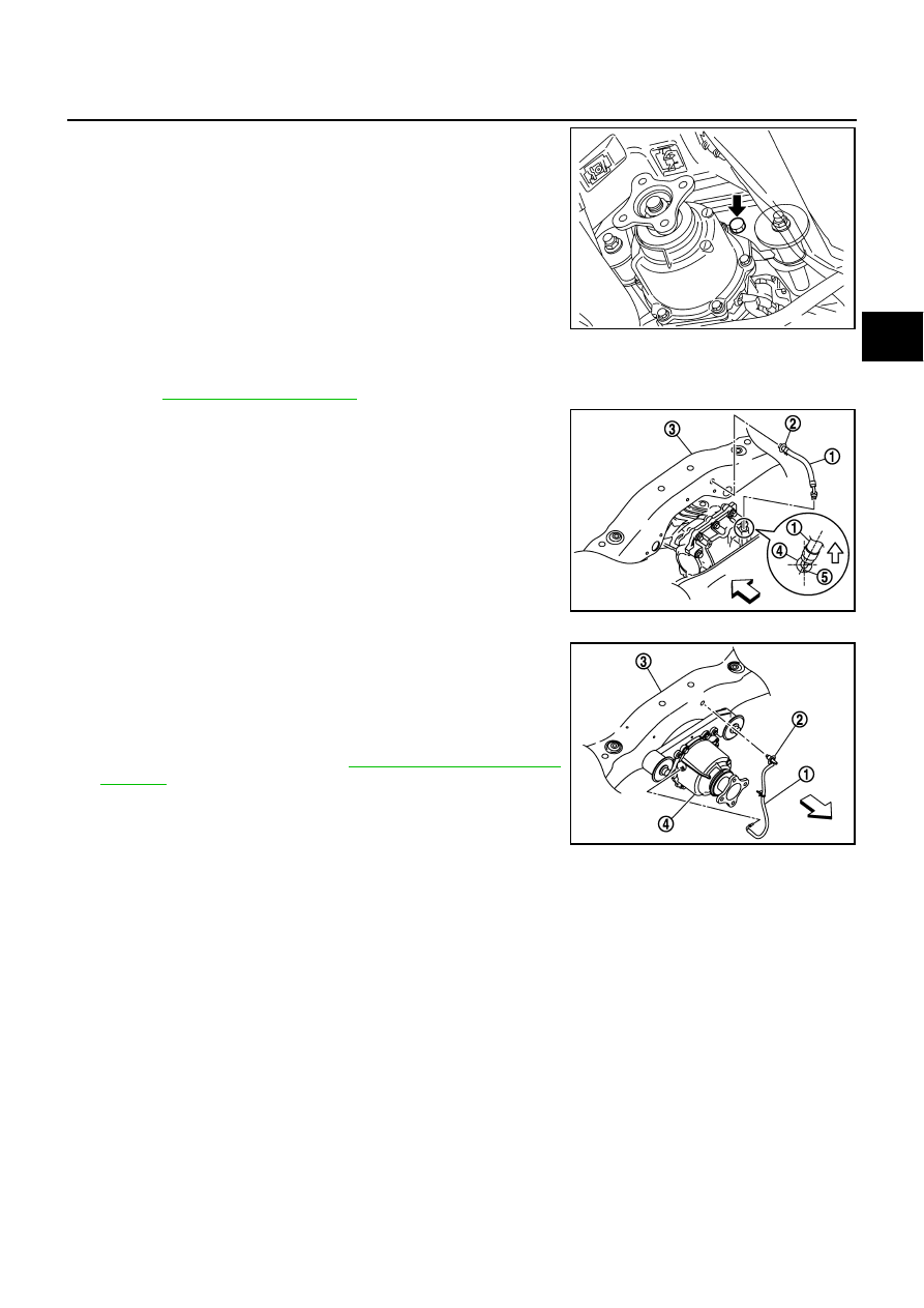
When installing breather hoses, refer to the figure and following.

CAUTION:

Make sure there are no pinched or restricted areas on the
breather hose caused by bending or winding when install-
ing it.

For installation of rear final drive breather hose (1), the vehicle
side end breather connector (2) shall be inserted to rear suspen-
sion member (3). Install metal connector (4) side of this hose to
rear cover by inserting it with aiming painted marking (5) to the
rear of vehicle.

CAUTION:

Do not reuse breather connector.

For installation of electric controlled coupling breather hose (1),
the vehicle side end breather connector (2) shall be inserted to
rear suspension member (3). Install its metal tube to rear final
drive assembly (4) and direct the metal tube hose side end to
the front of vehicle.

When oil leaks while removing final drive assembly, check oil
level after the installation. Refer to 

RFD-8, "Checking Differential

Gear Oil"

 .

CAUTION:

Do not reuse breather connector.

PDIA0040E

PDIA1104E

PDIA1105E

RFD-16

REAR FINAL DRIVE ASSEMBLY

Revision: 2005 August

2005 Murano

Disassembly and Assembly

ADS001BM

COMPONENTS

1.

Companion flange lock nut

2.

Companion flange

3.

Front oil seal

4.

Coupling cover

5.

Reamer bolt

6.

Coupling front bearing

7.

Electric controlled coupling

8.

AWD solenoid harness

9.

Center oil seal

10. Drive pinion nut

11.

Pinion front bearing

12. Gear carrier

13. Connector bracket

14. Collapsible spacer

15. Drive pinion adjusting shim

16. Pinion rear bearing

17. Drive pinion

18. Side oil seal

19. Side bearing adjusting shim

20. Side bearing

21. Drive gear

22. Differential case

23. Side gear thrust washer

24. Side gear

25. Pinion mate thrust washer

26. Pinion mate gear

27. Pinion mate shaft

28. Lock pin

29. Rear cover

30. Filler plug

31. Drain plug

32. Gasket

PDIA0816E

REAR FINAL DRIVE ASSEMBLY

RFD-17

C

E

F

G

H

I

J

K

L

M

A

B

RFD

Revision: 2005 August

2005 Murano

ASSEMBLY INSPECTION AND ADJUSTMENT
Total Preload Torque

1.

Remove electric controlled coupling assembly. Refer to 

RFD-21, "Electric Controlled Coupling Assembly"

.

2.

Rotate drive pinion back and forth 2 to 3 times to check for unusual noise and rotation malfunction.

3.

Rotate drive pinion at least 20 times to check for smooth opera-
tion of the bearing.

4.

Fit drive pinion socket onto drive pinion spline. Measure the total
preload, using the preload gauge.

NOTE:
Total preload torque = Pinion bearing torque + Side bearing torque

If measured value is out of the specification, disassemble it to check and adjust each part. Adjust the pin-
ion bearing preload and side bearing preload.
Adjust the pinion bearing preload first, then adjust the side bearing preload.

Drive Gear Runout

1.

Remove rear cover. Refer to 

RFD-22, "Differential Assembly"

 .

2.

Following the procedure below, install a dummy cover set to
gear carrier.

a.

Set dummy cover shims to the right and left side bearing adjust-
ing shims.

b.

Temporarily tighten dummy cover to gear carrier.

c.

Position dummy cover spacer to dummy cover.

d.

Tighten rear cover mounting bolts to the specified torque. Refer
to 

RFD-16, "COMPONENTS"

 .

e.

Tighten dummy cover spacer mounting bolts evenly to the spec-
ified torque.

Tool number

A: ST3127S000 (J-25765-A)

B: KV38108500 (

)

Total preload torque:

1.33 - 2.16 N·m (0.14 - 0.22 kg-m, 12 - 19 in-lb)

PDIA0048E

When the preload torque is large

On pinion bearings:

Replace the collapsible spacer.

On side bearings:

Use thinner side bearing adjusting shims. Refer to 

RFD-35, "Side 

Bearing Adjusting Shim"

 .

When the preload is small

On pinion bearings:

Tighten the drive pinion nut.

On side bearings:

Use thicker side bearing adjusting shims. Refer to 

RFD-35, "Side 

Bearing Adjusting Shim"

 .

Tool number

: KV381086S1 (

)

: 5.9 N·m (0.6 kg-m, 52 in-lb)

PDIA0474E

RFD-18

REAR FINAL DRIVE ASSEMBLY

Revision: 2005 August

2005 Murano

3.

Fit a dial indicator to the drive gear back face.

4.

Rotate the drive gear to measure runout.

If the runout is outside of the repair limit, check drive gear
assembly condition; foreign material may be caught between
drive gear and differential case, or differential case or drive gear
may be deformed, etc.

CAUTION:

Replace drive gear and drive pinion gear as a set.

Tooth Contact

1.

Remove rear cover. Refer to 

RFD-22, "Differential Assembly"

 .

2.

Attach dummy cover set. For dummy cover installation, refer to 

RFD-17, "Drive Gear Runout"

 .

3.

Apply red lead to drive gear.

CAUTION:

Apply red lead to both the faces of 3 to 4 gears at 4 loca-
tions evenly spaced on drive gear.

4.

Rotate drive gear back and forth several times, check drive pin-
ion gear to drive gear tooth contact.

CAUTION:

Check tooth contact on drive side and reverse side.

Runout limit:

0.05 mm (0.0020 in) or less

PDIA0050E

Tool number 

: KV381086S1 (

)

PDIA0051E

SDIA0570E

REAR FINAL DRIVE ASSEMBLY

RFD-19

C

E

F

G

H

I

J

K

L

M

A

B

RFD

Revision: 2005 August

2005 Murano

5.

If tooth contact is improperly adjusted, follow the procedure
below to adjust the pinion height (dimension X).

If the tooth contact is near the face (face contact), or near the
heal (heel contact), thicken drive pinion gear adjusting shims to
move drive pinion closer to drive gear.
Refer to 

RFD-35, "Drive Pinion Adjusting Shim"

 .

SDIA2549E

SDIA0517E

PDIA0440E

RFD-20

REAR FINAL DRIVE ASSEMBLY

Revision: 2005 August

2005 Murano

If the tooth contact is near the flank (flank contact), or near the
toe (toe contact), thin drive pinion gear adjusting shims to move
drive pinion farther from drive gear.
Refer to 

RFD-35, "Drive Pinion Adjusting Shim"

 .

Backlash

1.

Remove rear cover. Refer to 

RFD-22, "Differential Assembly"

 .

2.

Attach dummy cover set. For dummy cover installation, refer to 

RFD-17, "Drive Gear Runout"

 .

3.

Fit a dial indicator to the drive gear face to measure the back-
lash.

If the backlash is outside of the specified value, change the
thickness of side bearing adjusting shims.

Companion Flange Runout

1.

Fit a dial indicator onto the companion flange face (inner side of
the propeller shaft mounting bolt holes).

2.

Rotate companion flange to check for runout.

3.

Fit a test indicator to the inner side of companion flange (socket
diameter).

4.

Rotate companion flange to check for runout.

5.

If the runout value is outside the runout limit, follow the proce-
dure below to adjust.

a.

Check for runout while changing the phase between companion flange and drive pinion by 90

°

 step, and

search for the position where the runout is the minimum.

b.

If the runout value is still outside of the limit after the phase has been changed, replace companion flange.

c.

If the runout value is still outside of the limit after companion flange has been replaced, possible cause will
be an assembly malfunction of drive pinion and electric controlled coupling, malfunctioning coupling bear-
ing, or malfunctioning of electric controlled coupling.

PDIA0441E

Tool number 

: KV381086S1 (

)

Backlash:

0.10 - 0.15 mm (0.0039 - 0.0059 in)

When the backlash is large:

Make drive gear back adjusting shims thicker, and 
drive gear front adjusting shims thinner. Refer to 

RFD-

35, "Side Bearing Adjusting Shim"

 .

When the backlash is small:

Make drive gear back adjusting shims thinner, and 
drive gear front adjusting shims thicker. Refer to 

RFD-

35, "Side Bearing Adjusting Shim"

 .

PDIA0049E

Runout limit:

0.13 mm (0.0051 in) or less

Runout limit:

0.19 mm (0.0075 in) or less

PDIA0439E

REAR FINAL DRIVE ASSEMBLY

RFD-21

C

E

F

G

H

I

J

K

L

M

A

B

RFD

Revision: 2005 August

2005 Murano

DISASSEMBLY
Electric Controlled Coupling Assembly

1.

Remove connector bracket.

2.

Put matching mark on the thread edge of electric controlled cou-
pling. The matching mark should be in line with the matching
mark on companion flange.

CAUTION:

For matching mark, use paint. Do not damage electric con-
trolled coupling.

NOTE:
When replacing electric controlled coupling, matching mark is
not necessary.

3.

Remove companion flange lock nut, using a flange wrench.

4.

Remove companion flange.

5.

Remove coupling cover.

6.

Remove front oil seal from coupling cover, using flat-bladed
screwdriver.

CAUTION:

Be careful not to damage coupling cover.

7.

Remove electric controlled coupling assembly from drive pinion
in gear carrier.

8.

Remove AWD solenoid harness.

PDIA0455E

PDIA0442E

PDG0213D

PDIA0443E

RFD-22

REAR FINAL DRIVE ASSEMBLY

Revision: 2005 August

2005 Murano

9.

Remove coupling front bearing, using pullers and then take off
bearing shim from electric controlled coupling.

10. Remove center oil seal from gear carrier.

Differential Assembly

1.

Remove side oil seal from gear carrier and rear cover, using flat-
bladed screwdriver.

CAUTION:

Be careful not to damage gear carrier and rear cover.

2.

Remove rear cover mounting bolts.

3.

Set drifts to the right and left side bearing adjusting shims indi-
vidually. Press differential case assembly with side bearing to
remove gear carrier assembly and rear cover assembly.

CAUTION:

The pressure shall be as low as possible to remove gear
carrier assembly and rear cover assembly. The maximum
pressure shall be 10 kN (1 ton, 1.1 US ton, 1.0 Imp ton).

NOTE:
Differential case assembly, side bearings, and adjusting shims
are compressed and integrated in gear carrier and rear cover.

4.

Remove drain plug and filler plug.

5.

Remove side bearing adjusting shims and side bearing outer races.

CAUTION:

Mark the side bearing adjusting shims so that the original mounting positions (right/left) can be
identified later.

6.

Remove drive gear mounting bolts and then remove drive gear
from differential case.

PDIA0444E

PDG0216D

Tool number

: KV40100610 (J-26089)

PDIA0065E

PDIA0446E

REAR FINAL DRIVE ASSEMBLY

RFD-23

C

E

F

G

H

I

J

K

L

M

A

B

RFD

Revision: 2005 August

2005 Murano

7.

Remove side bearing inner races, using pullers and the drift.

8.

Pull the lock pin out of pinion mate shaft, using the pin punch.

9.

Remove pinion mate shaft, pinion mate gears, pinion mate
thrust washers, side gears, side gear thrust washers from differ-
ential case.

Drive Pinion Assembly

1.

Remove electric controlled coupling assembly. Refer to 

RFD-21, "Electric Controlled Coupling Assembly"

.

2.

Remove differential case assembly. Refer to 

RFD-22, "Differential Assembly"

 .

3.

Fit drive pinion socket onto drive pinion spline. Remove drive
pinion nut, using the pinion nut wrench.

Tool number

: ST33052000 (

)

PDIA0459E

Tool number

: ST23550000 (

PDIA0062E

SDIA0032J

Tool number

A: KV38108400 (

)

B: KV38108500 (

)

PDIA0054E

RFD-24

REAR FINAL DRIVE ASSEMBLY

Revision: 2005 August

2005 Murano

4.

Press drive pinion assembly out of gear carrier.

CAUTION:

Do not drop drive pinion assembly.

5.

Remove pinion front bearing inner race.

6.

Remove collapsible spacer.

7.

Remove pinion rear bearing inner race from drive pinion, using
pullers.

8.

Using a brass rod, tap pinion front bearing outer race evenly
from the 2 cutouts on gear carrier and remove pinion front bear-
ing outer race.

CAUTION:

Be careful not to damage gear carrier.

9.

Using a brass rod, tap drive pinion adjusting shim evenly from
the 2 cutouts on gear carrier and remove drive pinion adjusting
shims and pinion rear bearing outer race.

CAUTION:

Be careful not to damage the gear carrier.

INSPECTION AFTER DISASSEMBLY

Clean up the disassembled parts. Then, inspect if the parts are worn or damaged. If so, follow the measures
below.

PDIA0445E

PDIA0179E

SDIA0564E

Content

Conditions and Measures

Hypoid gear

If the gear teeth do not mesh or line-up correctly, determine the cause and adjust or replace as nec-
essary.

If the gears are worn, cracked, damaged, pitted or chipped (by friction) noticeably, replace with new 
drive gear and drive pinion as a set.

Bearing

If any chipped (by friction), pitted, worn, rusted or scratched mark, or unusual noise from the bearing 
is observed, replace as a bearing assembly (as a new set).

Side gear and Pinion mate 
gear

If any cracks or damage on the surface of the tooth is found, replace.

If any worn or chipped mark on the contact sides of the thrust washer is found, replace.

Side gear thrust washer and 
pinion mate thrust washer

If it is chipped (by friction), damaged, or unusually worn, replace.

Oil seal 

Whenever disassembled, replace.

If wear, deterioration of adherence (sealing force lips), or damage is detected on the lips, replace 
them.

Differential case

If any wear or crack on the contact sides of the differential case is found, replace.

Companion flange

If any chipped mark (about 0.1 mm, 0.004 in) or other damage on the contact sides of the lips of the 
companion flange is found, replace.

REAR FINAL DRIVE ASSEMBLY

RFD-25

C

E

F

G

H

I

J

K

L

M

A

B

RFD

Revision: 2005 August

2005 Murano

ASSEMBLY
Drive Pinion Assembly

1.

Install a drive pinion adjusting shim of the same thickness as
was installed prior to disassembly. Press pinion rear bearing
outer race into gear carrier, using the drift.

CAUTION:

At first, using a hammer, tap bearing outer race until it
becomes flush to gear carrier.

Do not reuse pinion rear bearing outer race.

2.

Press pinion front bearing outer race into gear carrier, using the
drift.

CAUTION:

At first, using a hammer, tap bearing outer race until it
becomes flush to gear carrier.

Do not reuse pinion front bearing outer race.

3.

Press pinion rear bearing inner race to drive pinion, using the
drift.

CAUTION:

Do not reuse pinion rear bearing inner race.

4.

After checking and adjusting the tooth contact and backlash of
the hypoid gear following the procedure below.

a.

Apply gear oil to the drive pinon rear bearing, and assemble the
drive pinion to the gear carrier.

CAUTION:

Do not assemble a collapsible spacer.

b.

Apply gear oil to drive pinon front bearing, and assemble pinion
front bearing inner race to drive pinion. Using the drifts and
press stand, press pinion front bearing inner race to drive pinon
as far as drive pinion nut can be tightened.

CAUTION:

Do not reuse pinion front bearing inner race.

c.

Temporarily tighten removed drive pinon nut to drive pinion.

NOTE:
Use removed drive pinon nut only for the preload measurement.

Tool number

: ST17130000 (

)

PDIA0056E

Tool number

: ST33230000 (J-25805-01)

PDIA0067E

Tool number

: ST23860000 (

)

Tool number

A: KV40100610 (J-26089)

B: ST38220000 (

)

C: ST23860000 (

)

PDIA0068E

PDIA0057E

RFD-26

REAR FINAL DRIVE ASSEMBLY

Revision: 2005 August

2005 Murano

d.

Fit the drive pinon socket onto the drive pinion spline. Using the
pinon nut wrench, tighten drive pinon nut to the specified pre-
load torque.

CAUTION:

Drive pinon nut is tightened with no collapsible spacer. Be
careful not to overtighten it. While measuring the preload,
tighten it by 5

°

 to 10

°

.

e.

Apply gear oil to side bearings, and install new side bearing
adjusting shims with the same thickness or re-install the old
ones to the same mounting position they were in prior to disas-
sembly. Install differential case assembly to gear carrier.

CAUTION:

The drifts shall be placed on the center of the adjusting
shims.

The pressure shall be as low as possible to install gear
carrier assembly to differential assembly. The maximum
pressure shall be 10 kN (1 ton, 1.1 US ton, 1.0 Imp ton).

If adjusting shims are installed by tapping, gear carrier may be damaged. Avoid tapping.

f.

Check and adjust the tooth contact. Refer to 

RFD-18, "Tooth Contact"

 .

g.

Check and adjust the backlash. Refer to 

RFD-20, "Backlash"

 .

h.

Remove dummy cover set, and remove differential case assembly.

i.

Remove drive pinion nut and press drive pinion assembly out of
gear carrier.

CAUTION:

Do not drop drive pinion assembly.

j.

Remove pinion front bearing inner race.

Tool number

A: KV38108400 (

)

B: KV38108500 (

)

C: ST3127S000 (J-25765-A) 

Drive pinion bearing preload:

0.69 - 1.18 N·m (0.07 - 0.12 kg-m, 7 - 10 in-lb)

PDIA0058E

Tool number

: KV40100610 (J-26089)

PDIA0064E

PDIA0445E

REAR FINAL DRIVE ASSEMBLY

RFD-27

C

E

F

G

H

I

J

K

L

M

A

B

RFD

Revision: 2005 August

2005 Murano

5.

Assemble collapsible spacer to drive pinion.

CAUTION:

Be careful of the mounting direction of collapsible
spacer.

Do not reuse collapsible spacer.

6.

Apply gear oil to drive pinon front bearing, and assemble pinion
front bearing inner race to drive pinion. Using the drifts and
press stand, press the pinion front bearing inner race to drive
pinon as far as drive pinion nut can be tightened.

CAUTION:

Do not reuse pinion front bearing inner race.

7.

Apply anti-corrosive oil to the thread and seat of drive pinion nut, and temporarily tighten drive pinion nut
to drive pinion.

CAUTION:

Do not reuse drive pinion nut.

8.

Fit drive pinon socket onto drive pinion spline. Using the pinon
nut wrench, adjust the drive pinion nut tightening torque and pin-
ion bearing preload torque.

CAUTION:

Adjust the lower limit of the drive pinion nut tightening
torque first.

If the preload torque exceeds the specified value, replace
collapsible spacer and tighten it again to adjust. Never
loosen drive pinion nut to adjust the preload torque.

After adjustment, rotate drive pinion back and forth 2 to 3
times to check for unusual noise, rotation malfunction,
and other malfunctions.

9.

Install differential case assembly. Refer to 

RFD-28, "Differential Assembly"

 .

CAUTION:

Do not install rear cover.

10. Install dummy cover set, and check drive gear runout, tooth contact, and backlash. Refer to 

RFD-17,

"Drive Gear Runout"

 , 

RFD-18, "Tooth Contact"

 , 

RFD-20, "Backlash"

 .

11. Remove dummy cover set, then install rear cover, and side oil seal. Refer to 

RFD-28, "Differential Assem-

bly"

 .

SDIA2525E

Tool number

A: KV40100610 (J-26089)

B: ST38220000 (

)

C: ST23860000 (

)

PDIA0057E

Tool number

A: KV38108400 (

)

B: KV38108500 (

)

C: ST3127S000 (J-25765-A)

Drive pinion nut tightening torque:

181 - 361 N·m (19 - 36 kg-m, 134 - 266 ft-lb)

Drive pinion bearing preload:

0.69 - 1.18 N·m (0.07 - 0.12 kg-m, 7 - 10 in-lb)

PDIA0058E

RFD-28

REAR FINAL DRIVE ASSEMBLY

Revision: 2005 August

2005 Murano

12. Check total preload torque. Refer to 

RFD-17, "Total Preload Torque"

 .

13. Install electric controlled coupling assembly. Refer to 

RFD-31, "Electric Controlled Coupling Assembly"

 .

14. Check companion flange runout. Refer to 

RFD-20, "Companion Flange Runout"

 .

Differential Assembly

1.

Install side gear thrust washers with the same thickness as the
ones installed prior to disassembly or reinstall the old ones on
the side gears.

2.

Install side gear and thrust washer into differential case.

3.

Align 2 pinion mate gears in diagonally opposite positions, then
rotate and install them into differential case after installing thrust
washer to pinion mate gear.

4.

Align the lock pin holes on differential case with shaft, and install
pinion mate shaft.

5.

Measure side gear end play following the procedure below, and select the appropriate side gear thrust
washers.

a.

Place differential case straight up so that side gear to be mea-
sured comes upward.

SDIA0193J

SDIA0036J

SDIA0037J

PDIA0460E

REAR FINAL DRIVE ASSEMBLY

RFD-29

C

E

F

G

H

I

J

K

L

M

A

B

RFD

Revision: 2005 August

2005 Murano

b.

Using thickness gauges, measure the clearance between side
gear back and differential case at 3 different positions, while
rotating side gear. Average the 3 readings, and then measure
the clearance. (Measure the clearance of the other side as well.)

CAUTION:

To prevent side gear from tilting, insert thickness gauges
with the same thickness from both sides.

c.

If the back clearance is outside the specification, use a thicker/
thinner side gear thrust washer to adjust. Refer to 

RFD-34,

"Side Gear Thrust Washer"

 .

CAUTION:

Select a side gear thrust washer for right and left individu-
ally.

6.

Drive a lock pin into pinion mating shaft, using the pin punch.

CAUTION:

Do not reuse lock pin.

7.

Press side bearing inner races to differential case, using the
drift.

CAUTION:

Do not reuse side bearing inner race.

8.

Apply thread locking sealant into the thread hole of drive gear.

Use Genuine Medium Strength Thread Locking Sealant or
equivalent. Refer to 

GI-47, "RECOMMENDED CHEMICAL

PRODUCTS AND SEALANTS"

 .

CAUTION:

The drive gear back and threaded holes shall be cleaned
and decreased sufficiently.

Side gear back clearance specification:

0.2 mm (0.008 in) or less.
(Each gear should rotate smoothly without excessive 
resistance during differential motion.)

When the back clearance is large:

Use a thicker thrust washer.

When the back clearance is small:

Use a thinner thrust washer.

Tool number

: ST23550000 (

)

SDIA0583E

PDIA0062E

Tool number

: KV40105020 (

PDIA0052E

SPD554

RFD-30

REAR FINAL DRIVE ASSEMBLY

Revision: 2005 August

2005 Murano

9.

Install drive gear to the differential case, and apply anti-corrosive
oil onto threads and seats on the mounting bolts, and then
tighten to the specified torque. Refer to 

RFD-16, "COMPO-

NENTS"

 .

10. Apply gear oil to side bearings, and install new side bearing

adjusting shims (2 pieces for one side) with the same thickness
as the ones installed prior to disassembly or re-install the old
ones, with side bearing outer race to differential case.
If side bearing adjusting shims have been already selected, use
them.

CAUTION:

Do not reuse side bearing outer race.

11. Set the drifts to the right and left side bearing adjusting shims

individually. Compress differential case assembly and side bear-
ing to install gear carrier assembly to differential case assembly.

CAUTION:

The drift shall be placed on the center of the adjusting
shims.

The pressure shall be as low as possible to install differ-
ential assembly into gear carrier assembly. The maximum
pressure shall be 10 kN (1 ton, 1.1 US ton, 1.0 Imp ton).

If the adjusting shims are installed by tapping, the gear
carrier may be damaged. Avoid tapping.

12. Install dummy cover set, check and adjust drive gear runout, tooth contact, backlash, and total preload

torque. Refer to 

RFD-17, "Drive Gear Runout"

 , 

RFD-18, "Tooth Contact"

 , 

RFD-20, "Backlash"

 , 

RFD-17,

"Total Preload Torque"

 .

13. Remove dummy cover set.

14. Apply liquid gasket to mating surface of rear cover. Overlap both

ends of the bead for at least 3 mm (0.12 in).

Use Genuine Silicone RTV or equivalent. Refer to 

GI-47,

"RECOMMENDED CHEMICAL PRODUCTS AND SEAL-
ANTS"

 .

CAUTION:

Remove old sealant adhering to the mounting surfaces.
Also remove any moisture, oil, or foreign material adhering
to the mounting surfaces.

15. Set the drifts to the right and left side bearing adjusting shims

individually. Compress differential case assembly and side bear-
ing to install rear cover.

CAUTION:

The drift shall be placed on the center of the adjusting
shims.

The pressure shall be as low as possible to install the
rear cover. The maximum pressure shall be 10 kN (1 ton,
1.1 US ton, 1.0 Imp ton).

If rear cover is forced in by tapping, rear cover may be
damaged by adjusting shims. Avoid tapping.

16. Tighten rear cover mounting bolts to the specified torque. Refer to 

RFD-16, "COMPONENTS"

 .

Tool number

: KV40100610 (J-26089)

PDIA0466E

PDIA0064E

PDIA0447E

Tool number

: KV40100610 (J-26089)

PDIA0065E


Content      ..     203      204      205      206     ..