Nissan Murano Z50 (2005 year). Manual - part 198


  Index      Manuals     Nissan Murano Z50 (2005 year) - Service and Repair Manual


Search            copyright infringement  


Content      ..     196      197      198      199     ..


Nissan Murano Z50 (2005 year). Manual - part 198


REAR PROPELLER SHAFT

PR-7

C

E

F

G

H

I

J

K

L

M

A

B

PR

Revision: 2005 August

2005 Murano

INSTALLATION

Note the following, and install in the reverse order of removal.

Align matching marks to install propeller shaft to final drive and transfer companion flanges, and then
tighten to specified torque. Refer to 

PR-5, "COMPONENTS"

 .

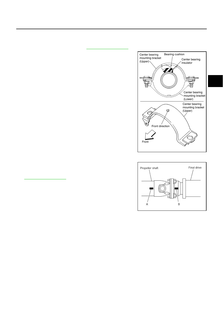
Adjust position of mounting bracket sliding back and forth to pre-
vent play in thrust direction of center bearing insulator. Install
bracket to vehicle.

After assembly, perform a driving test to check propeller shaft
vibration. If vibration occurred, separate propeller shaft from
final drive or transfer. Reinstall companion flange after rotating it
by 90, 180, 270 degrees. Then perform driving test and check
propeller shaft vibration again at each point.

If propeller shaft or final drive has been replaced, install them as follows;

1.

Install propeller shaft while aligning its matching mark A with the
matching mark B on the joint as close as possible.

2.

Tighten fixing bolts and nuts to the specified torque. Refer to

PR-5, "COMPONENTS"

 .

PDIA0017E

PDIA0423E

PR-8

SERVICE DATA AND SPECIFICATIONS (SDS)

Revision: 2005 August

2005 Murano

SERVICE DATA AND SPECIFICATIONS (SDS)

PFP:00030

General Specifications

ADS001BS

Journal Axial Play

ADS001BT

Propeller Shaft Runout

ADS001BU

Applied model

 VQ35DE

Propeller shaft model

3F63A-DOJ87

Number of joints

3

Coupling method with transfer

Flange type

Type of journal bearings

Shell type (Non-disassembly type)

Shaft length 

1st (Spider to cardan joint center)

1150 mm (45.28 in)

2nd (Cardan joint center to spider)

991 mm (39.02 in)

Shaft outer diameter

1st

75 mm (2.95 in)

2nd

75 mm (2.95 in)

Model

3F63A-DOJ87

Journal axial play

0 mm (0 in)

Model

3F63A-DOJ87

Propeller shaft runout limit

0.6 mm (0.024 in) or less

PS-1

POWER STEERING SYSTEM

G  STEERING

CONTENTS

C

D

E

F

H

I

J

K

L

M

SECTION 

PS

A

B

PS

Revision: 2005 August

2005 Murano

POWER STEERING SYSTEM

PRECAUTIONS .......................................................... 2

Precautions for Supplemental Restraint System 
(SRS) “AIR BAG” and “SEAT BELT PRE-TEN-
SIONER” .................................................................. 2
Precautions Necessary for Steering Wheel Rotation 
After Battery Disconnect  .......................................... 2

OPERATION PROCEDURE  ................................. 2

Precautions for Steering System  .............................. 3

PREPARATION ........................................................... 4

Special Service Tools (SST) ..................................... 4
Commercial Service Tools ........................................ 5

NOISE, VIBRATION AND HARSHNESS (NVH) 
TROUBLESHOOTING ................................................ 6

NVH Troubleshooting Chart  ..................................... 6

POWER STEERING FLUID ........................................ 7

Checking Fluid Level  ................................................ 7
Checking Fluid Leakage ........................................... 7
Air Bleeding Hydraulic System  ................................. 7

STEERING WHEEL  .................................................... 9

On-Vehicle Inspection and Service  .......................... 9

CHECKING CONDITION OF INSTALLATION  ...... 9
CHECKING STEERING WHEEL PLAY  ................ 9
CHECKING NEUTRAL POSITION ON STEER-
ING WHEEL  .......................................................... 9
CHECKING STEERING WHEEL TURNING 
FORCE .................................................................. 9
CHECKING FRONT WHEEL TURNING ANGLE 

... 10

Removal and Installation  ........................................ 10

STEERING COLUMN  ................................................11

Removal and Installation  .........................................11

COMPONENTS ...................................................11
REMOVAL ............................................................11
INSPECTION AFTER REMOVAL  ....................... 13
INSTALLATION ................................................... 13

INSPECTION AFTER INSTALLATION ................ 13

Disassembly and Assembly .................................... 14

DISASSEMBLY ................................................... 14
ASSEMBLY ......................................................... 14

POWER STEERING GEAR AND LINKAGE  ............ 15

Removal and Installation  ........................................ 15

REMOVAL ........................................................... 15
INSTALLATION ................................................... 18
INSPECTION AFTER INSTALLATION ................ 18

Disassembly and Assembly .................................... 19

COMPONENTS ................................................... 19
DISASSEMBLY ................................................... 20
INSPECTION AFTER DISASSEMBLY ................ 22
ASSEMBLY ......................................................... 23

POWER STEERING OIL PUMP  ............................... 27

On-Vehicle Inspection and Service ......................... 27

CHECKING RELIEF OIL PRESSURE  ................ 27

Removal and Installation  ........................................ 28

REMOVAL ........................................................... 28
INSTALLATION ................................................... 28

Disassembly and Assembly .................................... 28

COMPONENTS ................................................... 28
INSPECTION BEFORE DISASSEMBLY ............. 29
DISASSEMBLY ................................................... 29
INSPECTION AFTER DISASSEMBLY ................ 30
ASSEMBLY ......................................................... 30

HYDRAULIC LINE  .................................................... 33

Components ........................................................... 33
Removal and Installation  ........................................ 34

SERVICE DATA AND SPECIFICATIONS (SDS)  ...... 35

Steering Wheel  ....................................................... 35
Steering Angle  ........................................................ 35
Steering Column  ..................................................... 35
Steering Outer Socket and Inner Socket  ................ 35
Steering Gear  ......................................................... 36
Oil Pump ................................................................. 36
Steering Fluid .......................................................... 36

PS-2

PRECAUTIONS

Revision: 2005 August

2005 Murano

PRECAUTIONS

PFP:00001

Precautions for Supplemental Restraint System (SRS) “AIR BAG” and “SEAT 
BELT PRE-TENSIONER”

AGS000L7

The Supplemental Restraint System such as “AIR BAG” and “SEAT BELT PRE-TENSIONER”, used along
with a front seat belt, helps to reduce the risk or severity of injury to the driver and front passenger for certain
types of collision. This system includes seat belt switch inputs and dual stage front air bag modules. The SRS
system uses the seat belt switches to determine the front air bag deployment, and may only deploy one front
air bag, depending on the severity of a collision and whether the front occupants are belted or unbelted.
Information necessary to service the system safely is included in the SRS and SB section of this Service Man-
ual.

WARNING:

To avoid rendering the SRS inoperative, which could increase the risk of personal injury or death
in the event of a collision which would result in air bag inflation, all maintenance must be per-
formed by an authorized NISSAN/INFINITI dealer.

Improper maintenance, including incorrect removal and installation of the SRS, can lead to per-
sonal injury caused by unintentional activation of the system. For removal of Spiral Cable and Air
Bag Module, see the SRS section.

Do not use electrical test equipment on any circuit related to the SRS unless instructed to in this
Service Manual. SRS wiring harnesses can be identified by yellow and/or orange harnesses or
harness connectors.

Precautions Necessary for Steering Wheel Rotation After Battery Disconnect

AGS000R7

NOTE:

This Procedure is applied only to models with Intelligent Key system and NVIS/IVIS (NISSAN/INFINITI
VEHICLE IMMOBILIZER SYSTEM - NATS).

Remove and install all control units after disconnecting both battery cables with the ignition knob in the

LOCK

 position.

Always use CONSULT-II to perform self-diagnosis as a part of each function inspection after finishing
work. If DTC is detected, perform trouble diagnosis according to self-diagnostic results.

For models equipped with the Intelligent Key system and NVIS/IVIS, an electrically controlled steering lock
mechanism is adopted on the key cylinder.
For this reason, if the battery is disconnected or if the battery is discharged, the steering wheel will lock and
steering wheel rotation will become impossible.
If steering wheel rotation is required when battery power is interrupted, follow the procedure below before
starting the repair operation.

OPERATION PROCEDURE

1.

Connect both battery cables.

NOTE:
Supply power using jumper cables if battery is discharged.

2.

Use the Intelligent Key or mechanical key to turn the ignition switch to the 

ACC

 position. At this time, the

steering lock will be released.

3.

Disconnect both battery cables. The steering lock will remain released and the steering wheel can be
rotated.

4.

Perform the necessary repair operation.

5.

When the repair work is completed, return the ignition switch to the 

LOCK

 position before connecting

the battery cables. (At this time, the steering lock mechanism will engage.)

6.

Perform a self-diagnosis check of all control units using CONSULT-II. 

PRECAUTIONS

PS-3

C

D

E

F

H

I

J

K

L

M

A

B

PS

Revision: 2005 August

2005 Murano

Precautions for Steering System

AGS000CD

Before disassembly, thoroughly clean the outside of the unit.

Disassembly should be done in a clean work area. It is important to prevent the internal parts from becom-
ing contaminated by dirt or other foreign matter.

For easier and proper assembly, place disassembled parts in order on a parts rack.

Use nylon cloth or paper towels to clean the parts; common shop rags can leave lint that might interfere
with their operation.

Before inspection or reassembly, carefully clean all parts with a general purpose, non-flammable solvent.

Before assembly, apply a coat of recommended Genuine NISSAN PSF or equivalent to hydraulic parts.
Petroleum jelly may be applied to O-rings and seals. Do not use any grease.

Replace all gaskets, seals and O-rings. Avoid damaging O-rings, seals and gaskets during installation.
Perform functional tests whenever designated.

PS-4

PREPARATION

Revision: 2005 August

2005 Murano

PREPARATION

PFP:00002

Special Service Tools (SST)

AGS000CE

The actual shapes of Kent-Moore tools may differ from those of special service tools illustrated here.

Tool number
(Kent-Moore No.)
Tool name

Description

ST3127S000
(See J-25765-A)
Preload gauge
 1. GG9103000
    (J-25765-A)
    Torque wrench
 2. HT62940000
    (       –        )
   Socket adapter
 3. HT62900000
   (        –      )
   Socket adapter

Inspecting of sliding torque, steering torque, 
and rotating torque for ball joint

HT72520000
(J-25730-A)
Ball joint remover
a: 33 mm (1.30 in)
b: 50 mm (1.97 in)
r: 11.5 mm (0.453 in)

Removing steering outer socket

KV48104400
(J-46213)
Rear cover wrench
a: 19 mm (0.75 in)
b: 34.9 mm (1.374 in)

Removing rear cover

KV48104400
(        –        )
Teflon ring correcting tool
a: 50 mm (1.97 in) dia.
b: 36 mm (1.42 in) dia.
c: 100 mm (3.94 in)

Installing of rack Teflon ring

S-NT541

NT546

SGIA0516E

S-NT550

PREPARATION

PS-5

C

D

E

F

H

I

J

K

L

M

A

B

PS

Revision: 2005 August

2005 Murano

Commercial Service Tools

AGS000CF

KV48103400
(        –         )
Torque adapter

Inspecting rotating torque

1. KV48102500-04

(           —         )
Washer

2. KV48102500-01

(         —         )
Eye joint

3. KV48102500-03

(          —         )
Bolt

4. KV48102500-02

(          —         )
Flare Joint

5. KV48103500

(J26357 and J26357-10)

    Oil pressure gauge    

Measuring oil pump relief pressure

Tool number
(Kent-Moore No.)
Tool name

Description

ZZA0824D

SGIA0442E

Tool name

Description

Power tool

Removing tires

Removing undercover

Removing front exhaust tube

Removing stabilizer assembly

Removing engine mounting insulator

Removing member stay

Removing side splash guard

PBIC0190E

PS-6

NOISE, VIBRATION AND HARSHNESS (NVH) TROUBLESHOOTING

Revision: 2005 August

2005 Murano

NOISE, VIBRATION AND HARSHNESS (NVH) TROUBLESHOOTING

PFP:00003

NVH Troubleshooting Chart

AGS000CG

Use chart below to help you find the cause of the symptom. If necessary, repair or replace these parts.

×

: Applicable

Reference page

PS-

7

PS-

7

PS

-2

2

PS

-2

2

PS

-2

2

PS-

7

PS-

9

PS-

9

EM

-1

3

PS-

9

PS-

1

1

PS

-1

5

PS

-1

3

PS-

1

1

PS

-1

5

NVH in

 PR s

e

c

tio

n


NVH 

in

 RFD s

e

c

tio

n

NVH i

n

 F

AX, 

RAX

, FSU,

 RSU 

s

e

c

ti

o

n


NVH in

 W

T

 s

e

c

tio

n

NVH in

 W

T

 s

e

c

tio

n


NVH 

in

 F

AX s

e

c

tio

n

NVH in

 BR s

e

c

tio

n

Possible cause and suspected parts

F

lui

d l

e

vel

A

ir

 i

n

 hyd

rau

lic sys

te

m

T

ie-

rod 

bal

l j

o

in

t s

w

in

gi

ng 

fo

rc

e

T

ie-

rod 

bal

l j

o

in

t r

o

ta

ti

n

g

 t

o

rque

T

ie-

rod 

bal

l j

o

in

t e

nd 

pl

ay

S

teer

in

g f

lui

d l

e

a

k

age

S

teer

in

g w

h

eel

 p

la

y

S

teer

in

gear

 r

a

ck

 s

lid

ing 

fo

rc

e

D

ri

v

e bel

t l

oos

enes

s

Im

pr

oper

 s

te

e

ri

ng 

w

h

e

e

l

Im

pr

oper

 i

n

s

ta

lla

ti

o

n

 o

r l

o

ose

ness

 of

 t

ilt

 l

o

ck l

e

ver

M

o

u

n

ti

ng

 r

ubb

er

 det

er

io

ra

ti

on

S

teer

in

g col

u

m

n

 def

or

m

a

ti

on or

 da

m

a

ge

Im

pr

oper

 i

n

s

ta

lla

ti

o

n

 o

lo

ose

ness

 of

 st

eer

in

g

 c

o

lu

m

n

S

teer

in

g l

inka

ge l

o

osen

ess

P

R

OPE

LLER SHAFT

DIFFERENTIAL

A

X

LE and SUSPENSION

TI

R

E

S

ROAD W

H

EEL

DRIVE SHAFT

BR

AK

E

S

Symptom

STEERING

Noise

× × × × × × × × ×

× × × × × ×

×

Shake

× × ×

×

× × × ×

×

Vibration

× × × × ×

×

× ×

×

Shimmy

× × ×

×

× × ×

×

Judder

×

×

× × ×

×

POWER STEERING FLUID

PS-7

C

D

E

F

H

I

J

K

L

M

A

B

PS

Revision: 2005 August

2005 Murano

POWER STEERING FLUID

PFP:KLF20

Checking Fluid Level

AGS000CH

Stop engine before performing a fluid level check.

Ensure that fluid level is between the MAX range and MIN
range.

Because fluid level differs within the HOT range and the COLD
range, check it carefully.

CAUTION:

Do not overfill the Max range.

Do not reuse any used power steering fluid.

Recommended fluid is Genuine NISSAN PSF or equivalent.

Checking Fluid Leakage

AGS000CI

Check the lines for improper attachment and for leaks, cracks, dam-
age, loose connections, chafing or deterioration.

1.

Run engine until fluid temperature reaches 50 to 80

°

 C (122 to

176

°

F) in reservoir tank. Keep engine speed idle.

2.

Turn steering wheel right-to-left several times.

3.

Hold steering wheel at each “lock” position for five seconds to
check fluid leakage.

CAUTION:

Do not hold steering wheel in a locked position for more
than 10 seconds. (There is the possibility that oil pump may
be damaged.)

4.

If fluid leakage at connections is noticed, then loosen flare nut and then retighten. Do not over tighten con-
nector as this can damage O-ring, washer and connector.

5.

If fluid leakage from oil pump is noticed, check oil pump. Refer to 

PS-27, "POWER STEERING OIL

PUMP"

 .

6.

Check steering gear boots for accumulation of power steering fluid indicating a steering gear leak.

Air Bleeding Hydraulic System

AGS000CJ

Incomplete air bleeding causes the following to occur. When this happens, bleed air again.

Generation of air bubbles in reservoir tank.

Generation of clicking noise in oil pump.

Excessive buzzing in oil pump.

NOTE:
When vehicle is stationary or while steering wheel is being turned slowly, some noise may be heard from
oil pump or gear. This noise is normal and does not affect any system.

1.

Stop engine, and then turn steering wheel fully to right and left several times.

CAUTION:

Do not allow steering fluid reservoir tank to go below the low-level line. Check tank frequently and
add fluid as needed.

2.

Run engine at idle speed. Turn steering wheel fully to the right and then fully to the left, and keep for about
three seconds. Then check whether a fluid leakage has occurred.

3.

Repeat the 2nd procedure several times at about three seconds intervals.

HOT

: Fluid temperatures from 50 to 80 

°

C (122 to 

176

°

F)

COLD

: Fluid temperatures from 0 to 30

°

C (32 to 86

°

F)

SGIA0232J

SGIA0506E

PS-8

POWER STEERING FLUID

Revision: 2005 August

2005 Murano

CAUTION:

Do not hold steering wheel in a located position for more than 10 seconds. (There is the possibility
that oil pump may be damaged.)

4.

Check generation of air bubbles and cloud in fluid.

5.

If air bubbles and the cloud don't fade, stop engine, hold air bleeding until air bubbles and the cloud fade.
Perform the 2nd and the 3rd procedures again.

6.

Stop engine, check fluid level.

STEERING WHEEL

PS-9

C

D

E

F

H

I

J

K

L

M

A

B

PS

Revision: 2005 August

2005 Murano

STEERING WHEEL

PFP:48430

On-Vehicle Inspection and Service

AGS000CK

CHECKING CONDITION OF INSTALLATION

Check installation conditions of steering gear assembly, front suspension, axle and steering column.

Check if movement exists when steering wheel is moved up and down, to the left and right and to the axial
direction.

Check if the mounting bolts and nut for steering gear are loose
or not.

CHECKING STEERING WHEEL PLAY

1.

Set tires to the straight ahead, start engine, then turn steering wheel to the left and right lightly, and mea-
sure steering wheel movement on the outer circumference when steering wheel is turned up to the point
where tires start moving.

CHECKING NEUTRAL POSITION ON STEERING WHEEL

Check neutral position on steering wheel after confirming that front wheel alignment is correct. Refer to

FSU-5, "Wheel Alignment Inspection"

 .

1.

Set vehicle to the straight direction, check if steering wheel is in the neutral position.

2.

If it is not in the neutral position, remove steering wheel and reinstall it correctly.

3.

If the neutral position cannot adjust in the two teeth of steering gear assembly, loosen tie-rod lock nuts of
steering outer sockets, then adjust tie-rods by the same amount in the opposite direction.

CHECKING STEERING WHEEL TURNING FORCE

1.

Park vehicle on a level and dry surface, set parking brake.

2.

Remove driver air bag module from steering wheel. Refer to 

SRS-36, "DRIVER AIR BAG MODULE"

 .

3.

Start engine at idle, make steering fluid reach to normal operat-
ing temperature [50 to 80

°

C (122 to 176

°

F)], then check steering

wheel turning torque with pre-load gauge (SST).

4.

If steering wheel turning force is out of specification, check relief
hydraulic pressure of oil pump. Refer to 

PS-27, "POWER

STEERING OIL PUMP"

 .

End play of the axial direction for steering wheel

: 0 mm (0 in) 

Tightening torque

Bolt: 136 - 162 N·m (14 - 16 kg-m, 101 - 119 ft-lb)

Nut: 121.6 - 149.1 N·m (13 - 15, kg-m, 90 - 109 ft-lb)

SGIA0458E

Steering wheel play

: 0 - 35 mm (0 - 1.38 in)

Steering wheel turning force:

7.45 N·m (0.76 kg-m, 66 in-lb) or less

SGIA0459E

PS-10

STEERING WHEEL

Revision: 2005 August

2005 Murano

CHECKING FRONT WHEEL TURNING ANGLE 

Check front wheel turning angle after the toe-in inspection.
Place front wheels on turning radius gauges and rear wheels on
stands so that vehicle can be level. Check the maximum inner
and outer wheel turning angles for LH and RH road wheels.

Start engine and run at idle, turn steering wheel all the way right
and left, measure the turning angle.

Any turning angles are not adjustable. If any of steering angles
are out of the specification, check if the following parts are worn
or damaged.

Steering gear

Steering column

Front suspension components
If found that they are worn or damaged, replace them with new ones respectively.

Removal and Installation

AGS000CL

Refer to 

PS-11, "STEERING COLUMN"

 .

FAA0016D

Inner wheel (Angle: A)

Minimum

34

°

 30

 (34.5

°

)

Nominal

38

°

 00

 (38.0

°

)

Maximum

39

°

 00

 (39.0

°

)

Outer wheel (Angle: B)

Nominal

31

°

 30

 (31.5

°

)

SGIA0055E

STEERING COLUMN

PS-11

C

D

E

F

H

I

J

K

L

M

A

B

PS

Revision: 2005 August

2005 Murano

STEERING COLUMN

PFP:48810

Removal and Installation

AGS000CM

COMPONENTS

CAUTION:

Care must be taken not to give axial impact to steering column assembly during removal and
installation.

Care must be taken not to move steering gear during removal of steering column assembly.

REMOVAL

1.

Set vehicle to the straight ahead-direction.

2.

Remove driver air bag module from steering wheel. Refer to 

SRS-36, "DRIVER AIR BAG MODULE"

 .

3.

Disconnect steering switch connector, remove steering wheel lock nut, then remove steering wheel. Refer
to 

SRS-38, "SPIRAL CABLE"

 .

1.

Steering wheel lock nut

2.

Lid

3.

Steering wheel

4.

Combination switch and spiral cable 5.

Steering column assembly

6.

Hole cover seal

7.

Clamp

8.

Hole cover

9.

Lower joint

10. Tilt lever knob

SGIA0823E

PS-12

STEERING COLUMN

Revision: 2005 August

2005 Murano

4.

Remove fixing screw of tilt lever knob, then remove tilt lever
knob from tilt lever.

5.

Remove instrument driver lower panel. Refer to 

IP-10, "INSTRUMENT PANEL ASSEMBLY"

 .

6.

Remove steering column cover and ignition key finisher. Refer to 

IP-10, "INSTRUMENT PANEL ASSEM-

BLY"

 .

7.

Remove NATS antenna amp. Refer to 

BL-256, "How to Replace NATS Antenna Amp."

 .

8.

Remove fixing screws of knee protector, then remove knee pro-
tector from vehicle.

9.

Remove combination switch and spiral cable from steering column assembly. Refer to 

SRS-38, "SPIRAL

CABLE"

 .

10. Disconnect harness connector from each switch on steering column shaft, then separate vehicle side har-

ness from it.

11. Remove lock nut and bolt, then separate lower joint from upper

joint.

12. Remove fixing nuts from steering member, remove steering col-

umn assembly from steering member.

13. Remove hole cover seal and clamp.

14. Remove mounting nuts, then remove hole cover from dash panel.

SGIA0469E

SGIA0470E

SGIA0471E

SGIA0473E

STEERING COLUMN

PS-13

C

D

E

F

H

I

J

K

L

M

A

B

PS

Revision: 2005 August

2005 Murano

15. Raise vehicle, then remove mounting bolt (lower side) of lower

joint and remove lower joint from vehicle.

INSPECTION AFTER REMOVAL

Check if there is something wrong with jacket tube etc. And then if they are damaged, replace with new
one.

If vehicle is light shocked, check column length “L1” or “L2” as
shown in the figure. Then if it is out of the specified value,
replace with new one.

Check the turning torque of steering column with preload gauge (SST). If it is out of the specified value,
repair it or replace with new one.

INSTALLATION

Refer to 

PS-11, "Removal and Installation"

   for tightening torque. Install in the reverse order of removal.

NOTE:
Refer to component parts location and do not reuse non-reusable parts.

When installing steering column to steering member, install mounting nut from front side of vehicle.

INSPECTION AFTER INSTALLATION

After installing steering column to vehicle, check tilt device and
its operation range. Ranges of operation are shown in the figure.

Check if steering wheel operation can turn to the end of the left
and right smoothly.

SGIA0474E

Steering column length

           L1: 182 mm (7.17 in)

           L2: 242.6 mm (9.55 in)

SGIA0475E

Turning torque

: 0 - 0.2 N·m (0 - 0.02 kg-m, 0 - 2 in-lb)

SGIA0476E

PS-14

STEERING COLUMN

Revision: 2005 August

2005 Murano

Disassembly and Assembly

AGS000CN

DISASSEMBLY

1.

Remove spring from steering column assembly and tilt lever.

2.

Remove fixing bolt of upper joint, then remove upper joint from
steering column assembly.

ASSEMBLY

Refer to 

PS-14, "Disassembly and Assembly"

   for tightening torque. Install in the reverse order of

removal.

1.

Steering column assembly

2.

Spring

3.

Tilt lever knob

4.

Upper joint

SGIA0824E

SGIA0479E


Content      ..     196      197      198      199     ..