Nissan Murano Z50 (2005 year). Manual - part 199
POWER STEERING GEAR AND LINKAGE
PS-15
C
D
E
F
H
I
J
K
L
M
A
B
PS
Revision: 2005 August
2005 Murano
POWER STEERING GEAR AND LINKAGE
PFP:49001
Removal and Installation
AGS000CO
CAUTION:
Spiral cable may snap due to steering operation if steering column is separated from steering gear
assembly. Therefore fix steering wheel with a string to avoid turns.
REMOVAL
2WD
1.
Set wheels in the straight-ahead position.
2.
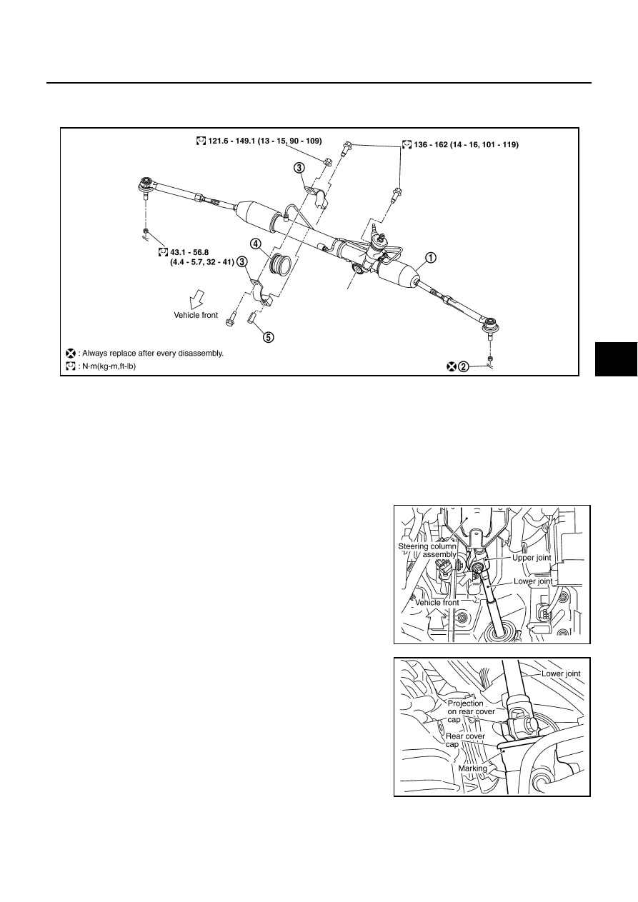
Remove lock nut and bolt, then separate lower joint from upper
joint.
3.
Remove tires from vehicle with power tool.
4.
Confirm slit of lower joint fits with the projection on rear cover
cap, furthermore marking position on steering gear assembly
nearly fits with the projection on rear cover cap.
5.
Remove cotter pin at steering knuckle, then loosen mounting
nut.
1.
Steering gear assembly
2.
Cotter pin
3.
Rack mounting bracket
4.
Rack mounting insulator
5.
Sleeve
SGIA0486E
SGIA0471E
SGIA0487E