Nissan Murano Z50 (2005 year). Manual - part 110
DTC P1274, P1284 A/F SENSOR 1
EC-515
C
D
E
F
G
H
I
J
K
L
M
A
EC
Revision: 2005 August
2005 Murano
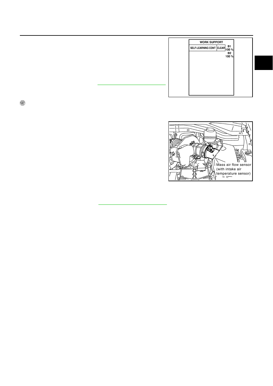
4.
Clear the self-learning coefficient by touching “CLEAR”.
5.
Turn ignition switch OFF and wait at least 10 seconds.
6.
Start engine and keep the engine speed between 3,500 and
4,000 rpm for 1 minute under no load.
7.
Let engine idle for 1 minute.
8.
Keep engine speed between 2,500 and 3,000 rpm for 20 min-
utes.
9.
If 1st trip DTC is detected, go to
EC-519, "Diagnostic Procedure"
.
WITH GST
1.
Start engine and warm it up to normal operating temperature.
2.
Turn ignition switch OFF and wait at least 10 seconds.
3.
Disconnect mass air flow sensor harness connector.
4.
Start engine and let it idle for at least 5 seconds.
5.
Stop engine and reconnect mass air flow sensor harness con-
nector.
6.
Select Service $03 with GST and make sure that DTC P0102 is
detected.
7.
Select Service $04 with GST and erase the DTC P0102.
8.
Start engine and keep the engine speed between 3,500 and
4,000 rpm for 1 minute under no load.
9.
Let engine idle for 1 minute.
10. Keep engine speed between 2,500 and 3,000 rpm for 20 min-
utes.
11. Select Service $07 with GST.
If 1st trip DTC is detected, go to
EC-519, "Diagnostic Procedure"
SEF968Y
PBIB1353E