Nissan Murano Z50 (2005 year). Manual - part 111
DTC P1276, P1286 A/F SENSOR 1
EC-531
C
D
E
F
G
H
I
J
K
L
M
A
EC
Revision: 2005 August
2005 Murano
Specification data are reference values and are measured between each terminal and ground.
CAUTION:
Do not use ECM ground terminals when measuring input/output voltage. Doing so may result in dam-
age to the ECM's transistor. Use a ground other than ECM terminals, such as the ground.
Diagnostic Procedure
ABS00A73
1.
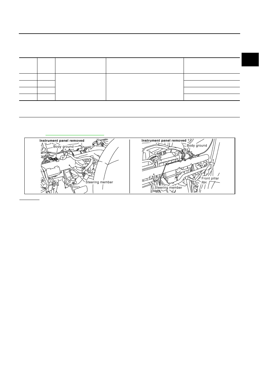
CHECK GROUND CONNECTIONS
1.
Turn ignition switch OFF.
2.
Loosen and retighten two ground screws on the body.
Refer to
OK or NG
OK
>> GO TO 2.
NG
>> Repair or replace ground connections.
TERMI-
NAL
NO.
WIRE
COLOR
ITEM
CONDITION
DATA (DC Voltage)
57
P
A/F sensor 1 (Bank 2)
[Engine is running]
●
Warm-up condition
●
Idle speed
Approximately 2.6V
58
SB
Approximately 2.3V
76
G/Y
Approximately 3.1V
77
LG
Approximately 2.3V
PBIB1835E