Nissan Murano Z50 (2005 year). Manual - part 9
TROUBLE DIAGNOSIS
ATC-105
C
D
E
F
G
H
I
K
L
M
A
B
ATC
Revision: 2005 August
2005 Murano
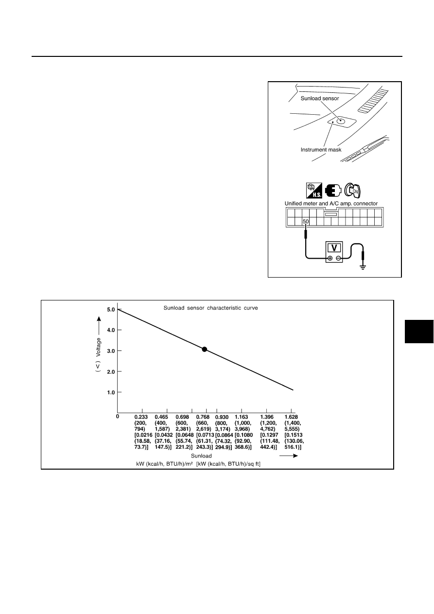
COMPONENT INSPECTION
Sunload Sensor
Measure voltage between unified meter and A/C amp. harness con-
nector M51 terminal 50 (O) and ground.
●
When checking sunload sensor, select a place where sun shines directly on it.
If NG, replace sunload sensor.
RJIA1807E
SHA930E