Nissan Murano Z50 (2005 year). Manual - part 7
TROUBLE DIAGNOSIS
ATC-73
C
D
E
F
G
H
I
K
L
M
A
B
ATC
Revision: 2005 August
2005 Murano
COMPONENT DESCRIPTION
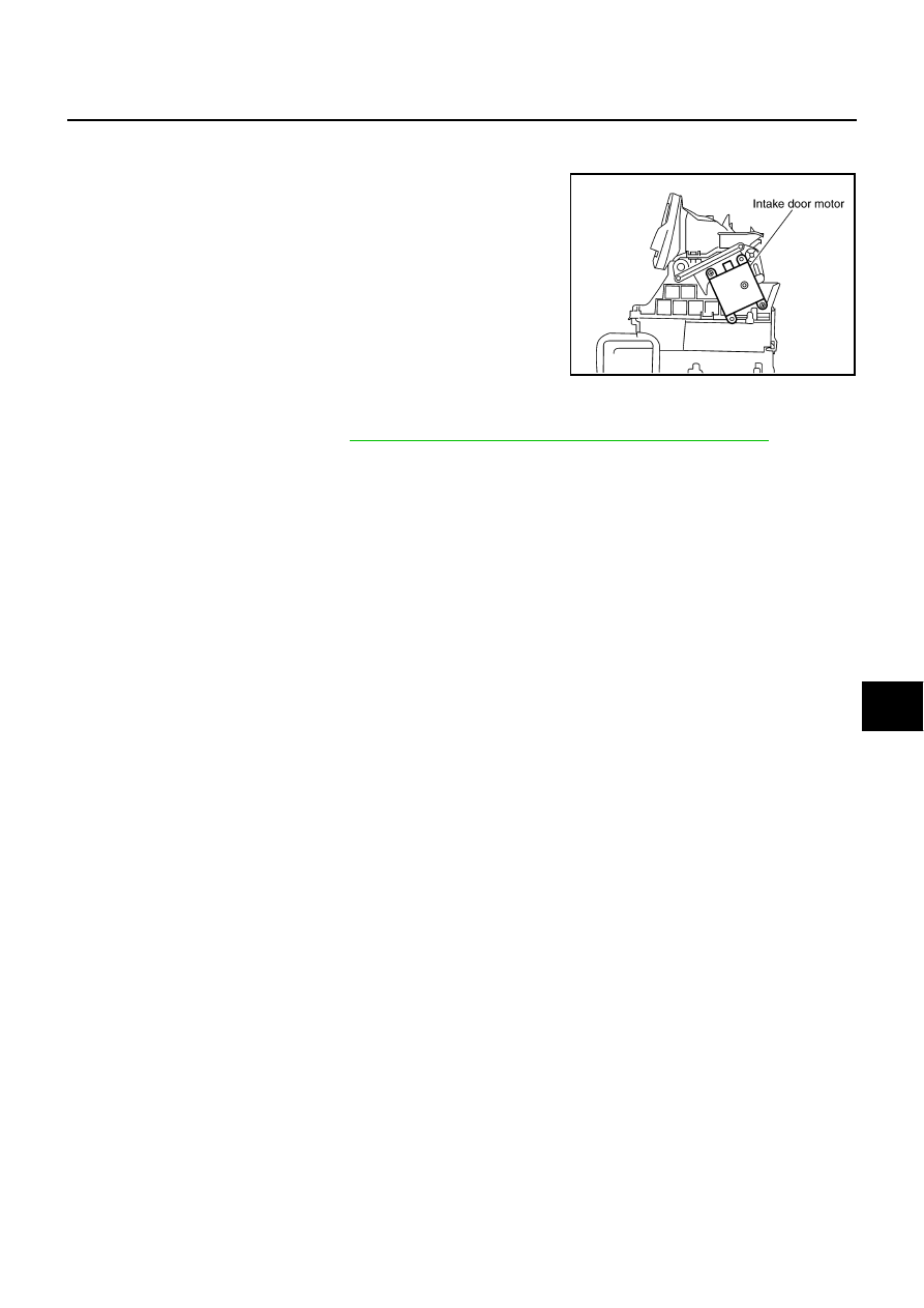
Intake Door Motor
The intake door motor is attached to the intake unit. It rotates so that
air is drawn from inlets set by the unified meter and A/C amp. Motor
rotation is conveyed to a lever which activates the intake door.
DIAGNOSIS PROCEDURE FOR INTAKE DOOR MOTOR
SYMPTOM: Intake door motor does not operate normally.
Perform diagnosis procedure. Refer to
ATC-61, "DIAGNOSIS PROCEDURE FOR LAN CIRCUIT"
.
RJIA1788E