Nissan Murano Z50 (2004 year). Manual - part 210


  Index      Manuals     Nissan Murano Z50 (2004 year) - Service and Repair Manual


Search            copyright infringement  


Content      ..     208      209      210      211     ..


Nissan Murano Z50 (2004 year). Manual - part 210


AUTOMATIC DRIVE POSITIONER

SE-77

C

D

E

F

G

H

J

K

L

M

A

B

SE

Revision: 2004 November

2004 Murano

3. 

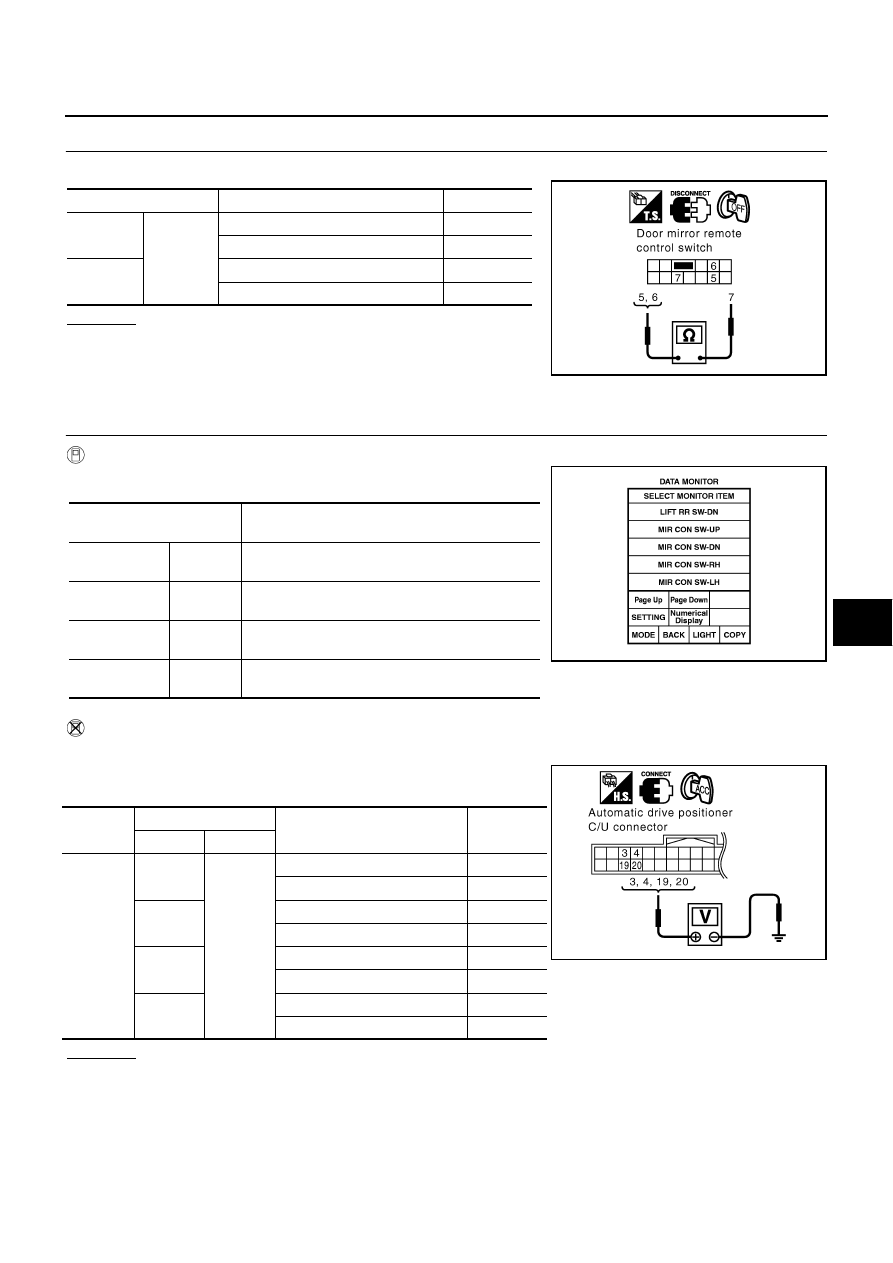
CHECK DOOR MIRROR REMOTE CONTROL SWITCH (CHANGEOVER SWITCH) 

Check continuity between door mirror remote control switch as follows.

OK or NG

OK

>> Check the condition of the harness and the connector.

NG

>> Replace door mirror remote control switch.

Door Mirror Remote Control Switch (Mirror Switch) Circuit Check

AIS003HH

1. 

CHECK DOOR MIRROR REMOTE CONTROL SWITCH(MIRROR SWITCH) SIGNAL 

 With CONSULT–II

Check the operation on “MIR CON SW–UP/DN” and
“MIR CON SW–RH/LH” in the DATA MONITOR.

 Without CONSULT–II

1.

Turn ignition switch ACC.

2.

Check voltage between automatic drive positioner control unit
connector and ground.

OK or NG

OK

>> Door mirror remote control switch (mirror switch) circuit is OK.

NG

>> GO TO 2.

Terminals

Condition

Continuity

5

7

Changeover switch RIGHT position

Yes

Changeover switch neutral position

No

6

Changeover switch LEFT position

Yes

Changeover switch neutral position

No

PIIA4770E

Monitor item [OPERATION 

or UNIT]

Contents

MIR CON SW
–UP

“ON/OFF”

ON/OFF status judged from the door mirror remote 
control switch (UP) signal is displayed.

MIR CON SW
–DN

“ON/OFF”

ON/OFF status judged from the door mirror remote 
control switch (DOWN) signal is displayed.

MIR CON SW
–RH

“ON/OFF”

ON/OFF status judged from the door mirror remote 
control switch (RIGHT) signal is displayed.

MIR CON SW
–LH

“ON/OFF”

ON/OFF status judged from the door mirror remote 
control switch (LEFT) signal s displayed.

PIIA0199E

Connector

Terminals (Wire color)

Condition

Voltage (V)

(Approx)

(+)

(-)

M19

3 (Y/B)

Ground

Mirror switch UP operation

0

Mirror switch neutral position

5

4 (V/W)

Mirror switch LEFT operation

0

Mirror switch neutral position

5

19 (L/O)

Mirror switch DOWN operation

0

Mirror switch neutral position

5

20 (V)

Mirror switch RIGHT operation

0

Mirror switch neutral position

5

PIIA4771E

SE-78

AUTOMATIC DRIVE POSITIONER

Revision: 2004 November

2004 Murano

2. 

CHECK HARNESS CONTINUITY

1.

Turn ignition switch OFF.

2.

Disconnect automatic drive positioner control unit and door mirror remote control switch connector.

3.

Check continuity between automatic drive positioner control unit connector M19 terminal 3 (Y/B), 4 (V/W),
19 (L/O), 20 (V) and door mirror remote control switch connector M66 terminal 1 (V), 2 (V/W), 3 (Y/B), 4
(L/O).

4.

Check continuity between automatic drive positioner control unit
connector M19 terminal 3 (Y/B), 4 (V/W), 19 (L/O), 20 (V) and
ground.

OK or NG

OK

>> GO TO 3.

NG

>> Repair or replace harness between automatic drove positioner control unit and door mirror remote

control switch.

3. 

CHECK DOOR MIRROR REMOTE CONTROL SWITCH (MIRROR SWITCH)

Check continuity between door mirror remote control switch as follows.

OK or NG

OK

>> Check the condition of the harness and connector.

NG

>> Replace door mirror remote control switch.

3 (Y/B) – 3 (Y/B)

:Continuity should exist.

4 (V/W) – 2 (V/W)

:Continuity should exist.

19 (L/O) – 4 (L/O)

:Continuity should exist.

20 (V) – 1 (V)

:Continuity should exist.

3 (Y/B) – Ground

:Continuity should not exist.

4 (V/W) – Ground

:Continuity should not exist.

19 (L/O) – Ground

:Continuity should not exist.

20 (V) – Ground

:Continuity should not exist.

PIIA4772E

Terminals

Switch condition

Continuity

1

7

Mirror switch RIGHT operation

Yes

Mirror switch neutral position

No

2

Mirror switch LEFT operation

Yes

Mirror switch neutral position

No

3

Mirror switch UP operation

Yes

Mirror switch neutral position

No

4

Mirror switch DOWN operation

Yes

Mirror switch neutral position

No

PIIA4773E

AUTOMATIC DRIVE POSITIONER

SE-79

C

D

E

F

G

H

J

K

L

M

A

B

SE

Revision: 2004 November

2004 Murano

Door Mirror Remote Control Switch Ground Circuit Check

AIS003HU

1. 

CHECK DOOR MIRROR REMOTE CONTROL SWITCH (CANGEOVER SWITCH) 

1.

Turn ignition switch OFF.

2.

Disconnect door mirror remote control switch.

3.

Check continuity between door mirror remote control switch as follows.

OK or NG

OK

>> Check the condition of the harness and the connector.

NG

>> Replace door mirror remote control switch.

2. 

CHECK DOOR MIRROR REMOTE CONTROL SWITCH GROUND CIRCUIT

Check continuity between door mirror remote control switch connector M66 terminal 7 (B) and ground.

OK or NG

OK

>> GO TO 2.

NG

>> Repair or replace harness between door mirror remote

control switch and ground.

Terminals

Condition

Continuity

5

7

Changeover switch RIGHT position

Yes

Changeover switch neutral position

No

6

Changeover switch LEFT position

Yes

Changeover switch neutral position

No

PIIA4770E

7 (B) - Ground

: Continuity should exist.

PIIA4769E

SE-80

AUTOMATIC DRIVE POSITIONER

Revision: 2004 November

2004 Murano

Seat Memory Switch Circuit Check

AIS003H3

1. 

CHECK FUNCTION

 With CONSULT-II

With “SET SW,MEMORY SW1, MEMORY SW2”, “SET SW” on the
DATA MONITOR, operate the switch to check ON/OFF operation. 

 Without CONSULT-II

GO TO 2.

OK or NG

OK

>> Seat memory switch circuit is OK.

NG

>> GO TO 2.

2. 

CHECK SEAT MEMORY SWITCH

1.

Turn ignition switch OFF.

2.

Disconnect seat memory switch connector.

3.

Check continuity between seat memory switch as follows.

OK or NG

OK

>> GO TO 3.

NG

>> Replace seat memory switch.

Monitor item [OPERATION or 

UNIT]

Contents

MEMORY SW1

“ON/OFF”

ON/OFF status judged from the seat 
memory switch 1 signal is displayed.

MEMORY SW2

“ON/OFF”

ON/OFF status judged from the seat 
memory switch 2 signal is displayed.

SET SW

“ON/OFF”

ON/OFF status judged from the setting 
switch signal is displayed.

PIIA0309E

Terminal

Condition

Continuity

1

4

Memory switch 1 ON

Yes.

Memory switch 1: OFF

No.

2

Memory switch 2: ON

Yes.

Memory switch 2: OFF

No.

3

Set switch: ON

Yes.

Set switch: OFF

No.

PIIA4575E

AUTOMATIC DRIVE POSITIONER

SE-81

C

D

E

F

G

H

J

K

L

M

A

B

SE

Revision: 2004 November

2004 Murano

3. 

CHECK HARNESS CONTINUITY

1.

Disconnect automatic drive positioner control unit connector.

2.

Check continuity between automatic drive positioner control unit
connector M19 terminals 9 (LG/B), 24 (R/Y), 25 (P/L) and seat
memory switch connector D3 terminals 1 (LG/B), 2 (P/L), 3 (R/
Y).

3.

Check continuity between automatic drive positioner control unit
connector M19 terminals 9 (LG/B), 24 (R/Y), 25 (P/L) and
ground.

OK or NG

OK

>> GO TO 4.

NG

>> Repair or replace harness between automatic drive positioner control unit and seat memory

switch.

4. 

CHECK SEAT MEMORY SWITCH GROUND CIRCUIT

Check continuity between seat memory switch D3 terminal 4 (B) and
ground.

OK or NG

OK

>> Replace automatic drive positioner control unit.

NG

>> Repair or replace harness between seat memory switch

and ground.

9 (LG/B) – 1 (LG/B)

: Continuity should exist.

24 (R/Y) – 3 (R/Y)

: Continuity should exist.

25 (P/L) – 2 (P/L)

: Continuity should exist.

9 (LG/B) – Ground

: Continuity should not exist.

24 (R/Y) – Ground

: Continuity should not exist.

25 (P/L) – Ground

: Continuity should not exist.

PIIA4576E

4 (B) – Ground

: Continuity should exist. 

PIIA4821E

SE-82

AUTOMATIC DRIVE POSITIONER

Revision: 2004 November

2004 Murano

Seat Memory Indicator Lamp Circuit Check

AIS003HA

1. 

CHECK FUNCTION

 With CONSULT-II

With “MEMORY SW INDCTR” in ACTIVE TEST, check operation.

 Without CONSULT-II

GO TO 2.

OK or NG

OK

>> Seat memory indicator lamp circuit is OK.

NG

>> GO TO 2.

2. 

CHECK SEAT MEMORY SWITCH POWER SUPPLY CIRCUIT

1.

Turn ignition switch OFF.

2.

 Disconnect seat memory switch connector.

3.

Check voltage between seat memory switch connector D3 ter-
minal 5 (Y/R) and ground.

OK or NG

OK

>> GO TO 3.

NG

>> Repair or replace harness between fuse block (J/B) and seat memory switch.

Test item

Description

MEMORY SW 
INDCTR

The memory switch indicator is lit by receiving the drive signal.

PIIA0319E

5 (Y/R) – Ground

: Battery voltage

PIIA4595E

AUTOMATIC DRIVE POSITIONER

SE-83

C

D

E

F

G

H

J

K

L

M

A

B

SE

Revision: 2004 November

2004 Murano

3. 

CHECK SEAT MEMORY INDICATOR CIRCUIT HARNESS CONTINUITY

1.

Disconnect automatic drive positioner control unit connector.

2.

Check continuity between automatic drive positioner control unit
connector M19 terminals 12 (GR/L), 13 (Y/G) and seat memory
switch connector D3 terminals 6 (GR/L), 7 (Y/G). 

3.

Check continuity between automatic drive positioner control unit
connector M19 terminals 12 (GR/L), 13 (Y/G) and ground.

OK or NG

OK

>> GO TO 4.

NG

>> Repair or replace harness between automatic drive positioner control unit and memory switch.

4. 

CHECK SEAT MEMORY SWITCH INDICATOR SIGNAL

Check voltage between automatic drive positioner control unit con-
nector M19 terminals 12 (GR/L), 13 (Y/G) and ground.

OK or NG

OK

>> Replace automatic drive positioner control unit.

NG

>> Replace seat memory switch.

Door Mirror Sensor Power Supply and Ground Circuit Check

AIS003HT

1. 

CHECK DOOR MIRROR SENSOR CIRCUIT HARNESS CONTINUITY

1.

Turn ignition switch OFF.

2.

Disconnect automatic drive positioner control unit connector and door mirror (driver side and passenger
side) connector.

3.

Check continuity between automatic drive positioner control unit connector M20 terminal 33 (W/L), 41 (Y)
and door mirror (driver side) connector D2 (driver side) D32 (passenger side) terminal 3 (W/L), 9 (Y).

4.

Check continuity between automatic drive positioner control unit
connector M20 terminal 33 (W/L), 41 (Y) and ground.

OK or NG

OK

>> GO TO 2.

NG

>> Repair or replace harness between automatic drive

positioner control unit and door mirror (driver side and passenger side)

12 (GR/L) – 6 (GR/L)

: Continuity should exist.

13 (Y/G) – 7 (Y/G)

: Continuity should exist.

12 (GR/L) – Ground

: Continuity should not exist.

13 (Y/G) – Ground

: Continuity should not exist.

PIIA4596E

12 (GR/L) – Ground

: Battery voltage

13 (Y/G) – Ground

: Battery voltage

PIIA4597E

33 (W/L) - 3 (W/L)

: Continuity should exist.

41 (Y) - 9 (Y)

: Continuity should exist.

33 (W/L) - Ground

: Continuity should not exist.

41 (Y) - Ground

: Continuity should not exist.

PIIA4780E

SE-84

AUTOMATIC DRIVE POSITIONER

Revision: 2004 November

2004 Murano

2. 

CHECK MIRROR SENSOR POWER SUPPLY

1.

Connector automatic drive positioner control unit connector and
door mirror (driver side).

2.

Turn ignition switch ACC.

3.

Check voltage between automatic drive positioner control unit
connector M20 terminal 33 (W/L) and ground.

OK or NG

OK

>> GO OT 3.

NG

>> Replace automatic drive positioner control unit.

3. 

CHECK MIRROR SENSOR GROUND CIRCUIT

1.

Turn ignition switch OFF.

2.

Check continuity between automatic drive positioner control unit
connector M20 terminal 41 (Y) and ground.

OK or NG

OK

>> Check the condition of the harness and connector.

NG

>> Replace automatic drive positioner control unit.

Detention Switch Circuit Check

AIS0040O

1. 

CHECK FUNCTION

 With CONSULT-II

Check that when the CVT selector lever is in P position, “DETENT
SW” on the DATA MONITOR becomes OFF.

 Without CONSULT-II

GO TO 2.

OK or NG

OK

>> Detention switch circuit is OK.

NG

>> GO TO 2.

33 (W/L) - Ground

: Approx. 5V

PIIA4778E

41 (Y) - Ground

: Continuity should exist.

PIIA4779E

Monitor item

 [OPERATION or UNIT]

Contents

DETENT SW

“ON/

OFF”

The selector lever position “P position (OFF)/other than P 
position (ON)” judged from the detente switch signal is 
displayed.

PIIA0291E

AUTOMATIC DRIVE POSITIONER

SE-85

C

D

E

F

G

H

J

K

L

M

A

B

SE

Revision: 2004 November

2004 Murano

2. 

CHECK DETENTION SWITCH POWER SUPPLY

1.

Do insert the key to key cylinder.

2.

Disconnect CVT device [detention switch (key)] connector.

3.

Check voltage between CVT device [detention switch (key)]
connector M57 terminal 5 (B/R) and ground.

OK or NG

OK

>> GO TO 4.

NG

>> GO TO 3.

3. 

CHECK DETENTION SWITCH HARNESS

1.

Turn ignition switch OFF.

2.

Disconnect CVT device [detention switch (key)] connector and
“key switch and key lock solenoid” connector.

3.

Check continuity between CVT device [detention switch (key)]
connector M57 terminal 5 (B/R) and key switch and key lock
solenoid connector M28 terminal 4 (B/R).

4.

Check continuity between CVT device [detention switch (key)]
connector M57 terminal 5 (B/R) and ground.

OK or NG

OK

>> Check the condition of the harness and connector.

NG

>> Repair or replace harness between CVT device [detention switch (key)] and key switch and key

lock solenoid.

4. 

CHECK DETENTION SWITCH

Check continuity between detection switch as follows.

OK or NG

OK

>> GO TO 5.

NG

>> Replace CVT device [detention switch (key)].

5 (B/R) – Ground

: Battery voltage.

PIIA8451E

5 (B/R) – 4 (B/R)

: Continuity should exist.

5 (B/R) – Ground

: Continuity should not exist.

PIIA4565E

Terminals

Condition

Continuity

5

6

P–position

Yes.

Other than P–position

No.

PIIA4566E

SE-86

AUTOMATIC DRIVE POSITIONER

Revision: 2004 November

2004 Murano

5. 

CHECK DETENTION SWITCH SIGNAL CIRCUIT HARNESS CONTINUITY

1.

Disconnect driver seat control unit connector.

2.

Check continuity between driver seat control unit connector
B303 terminal 21 (R/L) and CVT device [detention switch (key)]
connector M57 terminal 6 (L).

3.

Check continuity between driver seat control unit connector
B303 terminal 21 (R/L) and ground.

OK or NG

OK

>> Replace driver seat control unit.

NG

>> Repair or replace harness between automatic drive positioner control unit and CVT device [deten-

tion switch (key)].

Key Switch and Key Lock Solenoid Circuit Check

AIS003H1

1. 

CHECK KEY SWITCH AND KEY LOCK SOLENOID

 With CONSULT-II

Touch "BCM". With “IGN KEY SW” on the DATA MONITOR, Check
ON/OFF operation.

 *:Refer to 

SE-45, "DATA MONITOR"

 .

 Without CONSULT-II

GO TO 2.

OK or NG

OK

>> Key switch and key lock solenoid circuit is OK.

NG

>> GO TO 2.

2. 

KEY SWITCH AND KEY LOCK SOLENOID (KEY SWITCH) POWER SUPPLY CIRCUIT CHECK

1.

Turn ignition switch OFF.

2.

Check voltage between key switch and key lock solenoid con-
nector M28 terminal 3 (Y/R) and ground.

OK or NG

OK

>> GO TO 3.

NG

>> Check harness between key switch and key lock sole-

noid and fuse.

21 (R/L) – 6 (L)

: Continuity should exist.

21 (R/L) – Ground

: Continuity should not exist.

PIIA4567E

Monitor item [OPERA-

TION or UNIT]

Contents

IGN KEY SW*

“ON/

OFF”

Key inserted (ON)/key removed (OFF) status judged 
from the key-in detection switch is displayed.

PIIA0298E

3 (Y/R) – Ground

: Battery voltage.

PIIA3286E

AUTOMATIC DRIVE POSITIONER

SE-87

C

D

E

F

G

H

J

K

L

M

A

B

SE

Revision: 2004 November

2004 Murano

3. 

CHECK KEY SWITCH AND KEY LOCK SOLENOID (KEY SWITCH)

Check continuity between key switch and key lock solenoid (key
switch) as follows.

OK or NG

OK

>> GO TO 4.

NG

>> Replace key switch and key lock solenoid (key switch).

4. 

CHECK HARNESS CONTINUITY

1.

Check continuity between BCM connector M34 terminal 37 (B/R) and key switch and key lock solenoid
(key switch) connector M28 terminal 4 (B/R).

2.

Check continuity between BCM connector M34 terminal 37 (B/
R) and ground.

OK or NG

OK

>> Key switch and key lock solenoid circuit is OK.

NG

>> Repair or replace harness between key switch and key

lock solenoid (key switch) and BCM.

Terminals

Condition

Continuity

3

4

Key is inserted in ignition key cylinder.

Yes

Key is removed from ignition key cylinder. 

No

PIIA3044E

37 (B/R) – 4 (B/R)

: Continuity should exist.

37 (B/R) – Ground

: Continuity should not exist.

PIIB0891E

SE-88

AUTOMATIC DRIVE POSITIONER

Revision: 2004 November

2004 Murano

UART Communication Line Circuit Check

AIS003HB

1. 

CHECK UART LINE INPUT/OUTPUT SIGNAL 1

1.

Turn ignition switch OFF.

2.

Check signal between driver seat control unit connector and
ground, with oscilloscope.

OK or NG

OK

>> GO TO 2.

NG

>> Check the following.

When voltage waveform does not appear with a constant voltage (approx. 5V), replace driver
seat control unit.

When voltage waveform does not appear with a constant voltage (approx. 0V), replace auto-
matic driver seat control unit.

2. 

CHECK UART LINE INPUT/OUTPUT SIGNAL 2

Check signal between automatic driver positioner control unit con-
nector ground, with oscilloscope.

OK or NG

OK

>> GO TO 3.

NG

>> Check the following.

When voltage waveform does not appear with a constant voltage (approx. 5V), replace auto-
matic drive positioner control unit.

When voltage waveform does not appear with a constant voltage (approx. 0V),replace driver
seat control unit.

Connector

Terminals 

(Wire color)

Condition

Signal

(Reference value)

(+)

(–)

B303

17 (Y/L)

Ground

Pedal 
adjusting 
switch ON 
(FR or RR 
operation)

PIIA4599E

PIIA4814E

Connector

Terminals 

(Wire color)

Condition

Signal

(Reference value)

(+)

(–)

M19

10 (R)

Ground

Pedal 
adjusting 
switch ON 
(FR or RR 
operation)

PIIA4816E

PIIA4813E

AUTOMATIC DRIVE POSITIONER

SE-89

C

D

E

F

G

H

J

K

L

M

A

B

SE

Revision: 2004 November

2004 Murano

3. 

CHECK UART LINE HERNESS

1.

Disconnect driver seat control unit connector and automatic
drive positioner control unit connector.

2.

Check continuity between driver seat control unit connector
B303 terminal 1 (Y/W), 17 (Y/L) and automatic drive positioner
connector M19 terminal 10 (R), 26 (R/G).

3.

Check continuity between driver seat control unit connector
B303 terminal 1 (Y/W), 17 (Y/L) and ground.

OK or NG

OK

>> GO TO 4.

NG

>> Repair or replace harness between driver seat control unit and automatic drive positioner control

unit.

4. 

CHECK DRIVER SEAT CONTROL UNIT

Dose the automatic drive positioner operate, when the driver control unit exchanged?

OK or NG

OK

>> Replace automatic drive positioner control unit.

NG

>> Replace driver seat control unit. 

Lumber Support Circuit Check

AIS004VY

1. 

CHECK LUMBER SUPPORT SWITCH POWER SUPPLY

1.

Turn ignition switch OFF.

2.

Disconnect memory switch and lumber support switch connec-
tor.

3.

Check voltage between l"memory switch and lumber support
switch" connector B316 terminal 33D (R) and ground.

OK or NG

OK

>> GO TO 2.

NG

>> Repair or replace harness between fuse block (J/B) and l"memory switch and lumber support

switch". 

1 (Y/W) 

 10 (R)

: Continuity should exist.

17 (Y/L) 

 26 (R/G)

: Continuity should exist.

1 (Y/W) 

 Ground

: Continuity should not exist.

17 (Y/L) 

 Ground

: Continuity should not exist.

PIIA4598E

33D (R) – Ground:

: Battery voltage

PIIB0875E

SE-90

AUTOMATIC DRIVE POSITIONER

Revision: 2004 November

2004 Murano

2. 

CHECK LUMBER SUPPORT SWITCH

Check voltage between number support switch connector and ground.

OK or NG

OK

>> GO TO 3.

NG

>> Replace power seat switch.

3. 

CHECK LUMBER SUPPORT MOTOR HARNESS

1.

Disconnect lumber support motor connector.

2.

Check continuity between l"memory switch and lumber support
switch" connector B314 terminal 4 (L), 5 (W) and lumber support
motor connector B315 terminal 4 (L), 5 (W).

3.

Check continuity between l"memory switch and lumber support
switch" connector B159 terminal 4 (L), 5 (W) and ground.

OK or NG

OK

>> GO TO 4.

NG

>> Repair or replace harness between l"memory switch and lumber support switch" and lumber sup-

port motor.

4. 

CHECK LUMBER SUPPORT SWITCH GROUND CIRCUIT

Check continuity between lumber support switch connector B306
terminal 48D (B) and ground.

OK or NG

OK

>> Check the condition of the harness and connector.

NG

>> Repair or replace harness between l"memory switch and lumber support switch" and ground. 

Connector

Terminals

 (Wire color)

Condition

Voltage (V) 

(Approx.)

(+)

(-)

B314

4 (L)

Ground

Lumber support switch 
turned to forward

Battery voltage

Lumber support switch 
neutral position

0

5 (W)

Lumber support switch 
turned to backward

Battery voltage

Lumber support switch 
neutral position

0

PIIB0877E

4 (L) 

 4 (L)

: Continuity should exist.

5 (W) 

 5 (W)

: Continuity should exist.

4 (L) 

 Ground

: Continuity should not exist.

5 (W) 

 Ground

: Continuity should not exist.

PIIB0878E

48D (B) – Ground

: Continuity should exist.

PIIB0876E

POWER SEAT

SE-91

C

D

E

F

G

H

J

K

L

M

A

B

SE

Revision: 2004 November

2004 Murano

POWER SEAT

PFP:87016

Automatic Drive Positioner Interlocking Power Seat

AIS003HO

Automatic drive positioner interlocking power seat. Refer to

SE-12, "AUTOMATIC DRIVE POSITIONER"

  .

SE-92

POWER SEAT

Revision: 2004 November

2004 Murano

Schematic

AIS003HN

TIWA0529E


Content      ..     208      209      210      211     ..