Nissan Murano Z50 (2004 year). Manual - part 188


  Index      Manuals     Nissan Murano Z50 (2004 year) - Service and Repair Manual


Search            copyright infringement  


Content      ..     186      187      188      189     ..


Nissan Murano Z50 (2004 year). Manual - part 188


CHASSIS AND BODY MAINTENANCE

MA-29

C

D

E

F

G

H

I

J

K

M

A

B

MA

Revision: 2004 November

2004 Murano

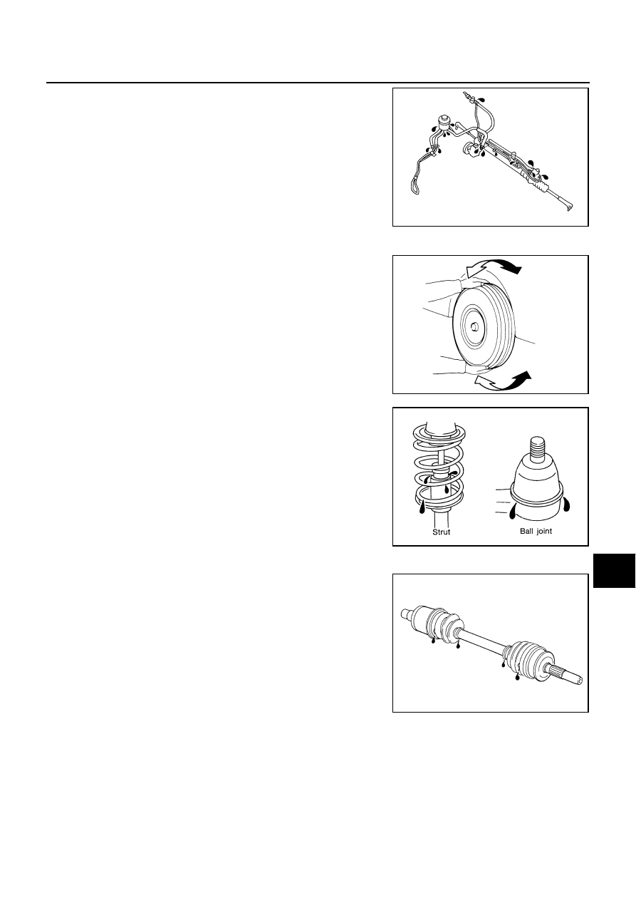
Check lines for improper attachment, leaks, cracks, dam-
age, loose connections, chafing and deterioration.

Check rack boots for accumulation of power steering fluid.

Axle and Suspension Parts

ALS000DZ

Check front and rear axle and suspension parts for excessive play,
cracks, wear or other damage.

Shake each wheel to check for excessive play.

Check wheel bearings for smooth operation.

Check axle and suspension nuts and bolts for looseness.

Check strut (shock absorber) for oil leakage or other damage.

Check suspension ball joint for grease leakage and ball joint
dust cover for cracks or other damage.

Drive Shaft

ALS000E0

Check boot and drive shaft for cracks, wear, damage and grease
leakage.

SST851C

SMA525A

SFA392B

SFA108A

MA-30

CHASSIS AND BODY MAINTENANCE

Revision: 2004 November

2004 Murano

Lubricating Locks, Hinges and Hood Latch

ALS000E1

Checking Seat Belt, Buckles, Retractors, Anchors and Adjusters

ALS000E2

PIIA4250E

PIIA4251E

SERVICE DATA AND SPECIFICATIONS (SDS)

MA-31

C

D

E

F

G

H

I

J

K

M

A

B

MA

Revision: 2004 November

2004 Murano

SERVICE DATA AND SPECIFICATIONS (SDS)

PFP:00030

Standard and Limit

ALS0008W

BELT DEFLECTION AND TENSION

*: If belt tension gauge cannot be installed at check points shown, check drive belt tension at different location on the belt.

ENGINE COOLANT CAPACITY (APPROXIMATE)

Unit: 

 (US qt, lmp qt)

RADIATOR

Unit: kPa (kg/cm

2

 , psi)

ENGINE OIL CAPACITY (APPROXIMATE)

Unit: 

  (US qt, lmp qt)

SPARK PLUG (PLATINUM-TIPPED TYPE)

Deflection adjustment

Unit: mm (in)

Tension adjustment*

Unit: N (kg, lb)

Used belt

New belt

Used belt

New belt

Limit

After adjustment

Limit

 After adjustment

Alternator and 
A/C compressor

       7 (0.28)

       4.2 - 4.6
    (0.17 - 0.18)

      3.7 - 4.1
   (0.15 - 0.16)

294 (30, 66)

730 - 818

(74.5 - 83.5,

164 - 184)

838 - 926

(85.5 - 94.5,

188 - 208)

Power steering 
oil pump

      11 (0.43)

        7.3 - 8
    (0.29 - 0.30)

      6.5 - 7.2
   (0.26 - 0.28)

196 (20, 44)

495 - 583

(50.5 - 59.5,

111 - 131)

603 - 691

(61.5 - 70.5, 

135.6 - 155.4)

Applied pushing 
force

98 N (10 kg, 22 lb)

 —

PBIC2449E

Engine coolant capacity (With reservoir tank at “MAX” level)

9.6  (10-1/8, 8-1/2)

Reservoir tank engine coolant capacity (At “MAX” level)

0.8  (7/8, 3/4)

Cap relief pressure

Standard

78 - 98 (0.8 - 1.0, 11 - 14)

Limit

59 (0.6, 9)

Leakage testing pressure

157 (1.6, 23)

Drain and refill 

With oil filter change

4.0 (4-1/4, 3-1/2)

Without oil filter change

3.7 (3-7/8, 3-1/4)

Dry engine (Overhaul)

5.0 (5-1/4, 4-3/8)

Make

NGK

Standard type

PLFR5A-11

Hot type

PLFR4A-11

Cold type

PLFR6A-11

Gap (nominal)

1.1 mm (0.043 in)

MA-32

SERVICE DATA AND SPECIFICATIONS (SDS)

Revision: 2004 November

2004 Murano

WHEEL BALANCE

Tightening Torque

ALS00096

Unit: N·m (kg-m, ft-lb)

Unit: N·m (kg-m, in-lb)*

Maximum allowable unbalance

Dynamic (At rim flange)

Less than 10 g (0.35 oz) (one side)

Static (At rim flange)

Less than 20 g (0.71 oz)

Drive belt idler pulley lock nut (A)

34.8 (3.5, 26)

Drive belt adjusting nut (B)

5.4 (0.55, 48)*

Drive belt adjusting bolt lock bolt (C)

28.0 (2.9, 21)

Power steering oil pump mounting bolt (D)

43.2 (4.4, 32)

Radiator drain plug

0.78 - 1.56 (0.08 - 0.15, 7 - 13)*

Oil pan drain plug

34.3 (3.5, 25)

Oil filter

17.6 (1.8, 13)

Spark plug

24.5 (2.5, 18)

PB-2

PARKING BRAKE SYSTEM

Revision: 2004 November

2004 Murano

PARKING BRAKE SYSTEM

PFP:36010

On-Vehicle Service

AFS00182

PEDAL STROKE

When parking brake pedal is operated with a force of 196 N (20 kg, 44 lb), make sure the stroke is within
the specified number of notches. (Check it by listening and counting the ratchet clicks.)

INSPECT COMPONENTS

Make sure the components are attached properly (check for looseness, backlash, etc.).

Check parking brake pedal assembly for bend, damage and cracks, and replace if necessary.

Check cable for wear and damage, and replace if necessary.

Check parking brake warning lamp switch for malfunction, and replace if necessary.

ADJUSTMENT

To perform adjustment operations, remove tire from the vehicle with power tool.

1.

Insert a deep socket wrench to rotate adjusting nut and loosen
the cable sufficiently. Then, return the pedal to the free height.

2.

Using wheel nuts, fix the disc to the hub and prevent it from tilt-
ing.

3.

Remove adjusting hole plug installed on the disc rotor. Using a
screwdriver, turn the adjuster as shown in the figure until the
disc rotor is locked. After locking, turn the adjuster in the oppo-
site direction by 5 or 6 notches.

4.

Rotate the disc rotor to make sure there is no drag. Install the
adjusting hole plug.

5.

Adjust cable as follows:

a.

Operate pedal 10 or more times with a force of 294 N (30 kg, 66
lb).

b.

Rotate adjusting nut with deep socket to adjust pedal stroke.

NOTE:
Do not reuse the adjusting nut after removing it.

c.

When parking brake pedal is operated with a force of 196 N (20 kg, 44 lb), make sure the stroke is within
the specified number of notches. (Check it by listening and counting the ratchet clicks.)

d.

With the pedal completely returned, make sure there is no drag on the rear brake.

Pedal stroke

: 3 to 4 notches

PFIA0414E

Pedal stroke

: 3 to 4 notches

PFIA0295E

PARKING BRAKE CONTROL

PB-3

C

D

E

G

H

I

J

K

L

M

A

B

PB

Revision: 2004 November

2004 Murano

PARKING BRAKE CONTROL

PFP:36010

Components

AFS00183

Removal and Installation

AFS00184

REMOVAL

1.

Remove front kicking plate (driver side). Refer to 

EI-32, "BODY SIDE TRIM"

  .

2.

Remove front body side welt (driver side). Refer to 

EI-32, "BODY SIDE TRIM"

  .

3.

Remove instrument lower panel (driver side). Refer to 

IP-10, "INSTRUMENT PANEL ASSEMBLY"

  .

4.

Remove dash side finisher (driver side). Refer to 

EI-32, "BODY SIDE TRIM"

  .

5.

Remove side ventilator assembly (Left). Refer to 

IP-10, "INSTRUMENT PANEL ASSEMBLY"

  .

6.

Remove relay box stay fixing screw.

7.

Remove parking brake switch connector.

8.

Remove adjusting nut.

9.

Remove device assembly bolt, nut and remove device assembly from the vehicle.

10. Remove center console. Refer to 

IP-17, "CENTER CONSOLE ASSEMBLY"

  .

11. Remove front cable mounting bolts, nuts and remove front cable from the vehicle.

12. Remove center muffler. Refer to 

EX-3, "EXHAUST SYSTEM"

  .

13. Remove propeller shaft with AWD model. Refer to 

PR-4, "REAR PROPELLER SHAFT"

  .

14. Remove disc rotors. Refer to 

BR-34, "Removal and Installation of Brake Caliper Assembly"

  .

15. Remove rear cable from the toggle lever.

1.

Device assembly

2.

Front cable

3.

Return spring

4.

Rear right cable

5.

Rear left cable

6.

Pin

7.

Pin

8.

Adjusting nut

9.

Spring cap

PFIA0415E

PB-4

PARKING BRAKE CONTROL

Revision: 2004 November

2004 Murano

16. Remove right and left rear cables mounting nuts, bolts, and remove right and left rear cable assembly

from the vehicle.

INSTALLATION

1.

Refer to “Component Parts Location” for tightening torque. Install in the reverse order of removal.

NOTE:
Do not reuse the adjusting nut.

2.

Adjust the parking brake. Refer to 

PB-2, "ADJUSTMENT"

  .

PARKING BRAKE SHOE

PB-5

C

D

E

G

H

I

J

K

L

M

A

B

PB

Revision: 2004 November

2004 Murano

PARKING BRAKE SHOE

PFP:44060

Components

AFS00185

Removal and Installation

AFS00186

REMOVAL

CAUTION:

Clean dust on the disc and back plate with a vacuum dust collector. Do not blow with compressed air.
Be careful of the following:

Remove the disc rotor only with the parking brake pedal completely in the returned position.

If disc rotor cannot be removed, remove as follows.

1.

Fix the disc rotor in place with wheel nuts and remove disc rotor
plug. Using a flat-bladed screwdriver, rotate adjuster wheel on
the adjuster assembly in direction B to retract and loosen brake
shoes.

1.

Return spring

2.

Adjuster assembly

3.

Shoe (Secondary)

4.

Shoe (Primary)

5.

Anti-rattle pin

6.

Retainer

7.

Anti-rattle spring

8.

Toggle lever

PFIA0443E

PFIA0309E

PB-6

PARKING BRAKE SHOE

Revision: 2004 November

2004 Murano

INSPECTION AFTER REMOVAL

Lining Thickness Inspection

Check thickness of lining. 

Drum Inner Diameter Inspection

Check drum inner diameter.

Other Inspections

Check shoe sliding surface for excessive wear and damage.

Check anti-rattle pin for excessive wear and corrosion.

Check return spring for sagging.

Does the adjustor move smoothly?

Check either visually or with a vernier caliper to see if there is any excessive wear, cracks, or damage
inside the drum.

INSTALLATION

Be careful of the following.

Refer to “Component Parts Location” and apply brake grease to the specified points during assembly.

There is difference of the adjusters orientation difference
between left and right. Assemble the adjuster so that threaded
part expands when rotating it in the direction shown by the
arrow.

Shorten adjuster by rotating it.

When disassembling the adjuster, apply PBC (Poly Butyl Cupry-
sil) grease or silicone based grease to the threads.

After replacing brake shoes or disc rotors, or if brakes do not
function well, perform break-in operation as follows.

1.

Adjust the parking brake pedal stroke to the specified stroke.

2.

Perform break-in (drag run) operation by driving the vehicle
under the following conditions:

3.

After break-in operation, check lever stroke of the parking brake. Readjust if it is no longer at the specified
stroke.

To prevent the lining from getting too hot, allow a cool off period of approximately 5 minutes after every
break-in operation.

Do not perform excessive break-in operations, because it may cause uneven or early wear of the lining.

Standard

Standard thickness (A)

: 3.2 mm (0.126 in)

Repair limit thickness (A)

: 1.5 mm (0.059 in)

SBR021A

Standard

Standard inner diameter

: 190 mm (7.48 in)

Maximum inner diameter

: 191 mm (7.52 in)

SBR768A

Drive forward

Vehicle speed approx. 40 km/h (25 MPH) set (forward)

Parking brake operating force approx. 147 N (15 kg, 33 lb) set

Distance approx. 100 m (328 ft)

SFIA0153E

SERVICE DATA AND SPECIFICATIONS (SDS)

PB-7

C

D

E

G

H

I

J

K

L

M

A

B

PB

Revision: 2004 November

2004 Murano

SERVICE DATA AND SPECIFICATIONS (SDS)

PFP:00030

Parking Drum Brake 

AFS00187

Parking Brake Control

AFS00188

Type

DS19HC

Brake lining

Standard thickness (new)

3.2 mm (0.126 in)

Wear limit thickness

1.5 mm (0.059 in)

Drum (disc)

Standard inner diameter (new)

190 mm (7.48 in)

Wear limit of inner diameter

191 mm (7.52 in)

Control type

Foot pedal

Number of notches [under force of 196 N (20 kg, 44 lb)]

3 to 4 notches

Number of notches
when warning lamp switch comes on

1 notches

PB-8

SERVICE DATA AND SPECIFICATIONS (SDS)

Revision: 2004 November

2004 Murano

PG-1

POWER SUPPLY, GROUND & CIRCUIT ELEMENTS

K  ELECTRICAL

CONTENTS

C

D

E

F

G

H

I

J

L

M

SECTION 

PG

A

B

PG

Revision: 2004 November

2004 Murano

POWER SUPPLY, GROUND & CIRCUIT ELEMENTS

POWER SUPPLY ROUTING CIRCUIT  ...................... 3

Schematic ................................................................ 3
Wiring Diagram - POWER -  ..................................... 4

BATTERY POWER SUPPLY - IGNITION SW. IN 
ANY POSITION ..................................................... 4
ACCESSORY POWER SUPPLY - IGNITION SW. 
IN “ACC” OR “ON”  ................................................ 9
IGNITION POWER SUPPLY - IGNITION SW. IN 
“ON” AND/OR “START” ....................................... 10

Fuse ....................................................................... 16
Fusible Link  ............................................................ 16
Circuit Breaker  ....................................................... 16

IPDM E/R (INTELLIGENT POWER DISTRIBUTION 
MODULE ENGINE ROOM)  ...................................... 17

System Description  ................................................ 17

SYSTEMS CONTROLLED BY IPDM E/R ........... 17
CAN COMMUNICATION LINE CONTROL  ......... 17
IPDM E/R STATUS CONTROL  ........................... 18

CAN Communication System Description .............. 18
CAN Communication Unit  ...................................... 18
Function of Detecting Ignition Relay Malfunction ... 18
CONSULT-II ........................................................... 19

CONSULT-II INSPECTION PROCEDURE  ......... 19
SELF-DIAG RESULTS  ........................................ 20
DATA MONITOR  ................................................. 21
ACTIVE TEST  ..................................................... 22

Auto Active Test  ..................................................... 23

DESCRIPTION .................................................... 23
OPERATION PROCEDURE  ............................... 23
INSPECTION IN AUTO ACTIVE TEST MODE ... 23

Schematic .............................................................. 25
IPDM E/R Terminal Arrangement  ........................... 26
IPDM E/R Power/Ground Circuit Inspection  .......... 27
Inspection With CONSULT-II (Self-Diagnosis)  ....... 28
Removal and Installation of IPDM E/R  ................... 29

REMOVAL ........................................................... 29
INSTALLATION ................................................... 29

GROUND ................................................................... 30

Ground Distribution ................................................. 30

MAIN HARNESS  ................................................. 30
ENGINE ROOM HARNESS  ................................ 33
ENGINE CONTROL HARNESS .......................... 35
BODY HARNESS  ................................................ 36
BODY NO.2 HARNESS  ...................................... 38

HARNESS ................................................................. 39

Harness Layout  ...................................................... 39

HOW TO READ HARNESS LAYOUT  ................. 39
OUTLINE ............................................................. 40
MAIN HARNESS  ................................................. 41
ENGINE ROOM HARNESS  ................................ 43
ENGINE CONTROL HARNESS .......................... 46
BODY HARNESS  ................................................ 48
BODY NO.2 HARNESS  ...................................... 50
ROOM LAMP HARNESS  .................................... 51
FRONT DOOR HARNESS  .................................. 52
REAR DOOR HARNESS  .................................... 53
BACK DOOR HARNESS  .................................... 54

Wiring Diagram Codes (Cell Codes)  ...................... 55

ELECTRICAL UNITS LOCATION  ............................ 58

Electrical Units Location  ......................................... 58

ENGINE COMPARTMENT  .................................. 58
PASSENGER COMPARTMENT  ......................... 59
LUGGAGE COMPARTMENT  .............................. 61

HARNESS CONNECTOR  ......................................... 62

Description .............................................................. 62

HARNESS CONNECTOR (TAB-LOCKING 
TYPE) .................................................................. 62
HARNESS CONNECTOR (SLIDE-LOCKING 
TYPE) .................................................................. 63

ELECTRICAL UNITS  ................................................ 64

Terminal Arrangement  ............................................ 64

SMJ (SUPER MULTIPLE JUNCTION)  ..................... 66

Terminal Arrangement  ............................................ 66

STANDARDIZED RELAY .......................................... 67

Description .............................................................. 67

NORMAL OPEN, NORMAL CLOSED AND 

POWER SUPPLY ROUTING CIRCUIT

PG-3

C

D

E

F

G

H

I

J

L

M

A

B

PG

Revision: 2004 November

2004 Murano

POWER SUPPLY ROUTING CIRCUIT

PFP:24110

Schematic

AKS007HE

TKWA1741E

PG-4

POWER SUPPLY ROUTING CIRCUIT

Revision: 2004 November

2004 Murano

Wiring Diagram - POWER -

AKS007HF

BATTERY POWER SUPPLY - IGNITION SW. IN ANY POSITION

TKWA1742E


Content      ..     186      187      188      189     ..