Nissan Murano Z50 (2004 year). Manual - part 178
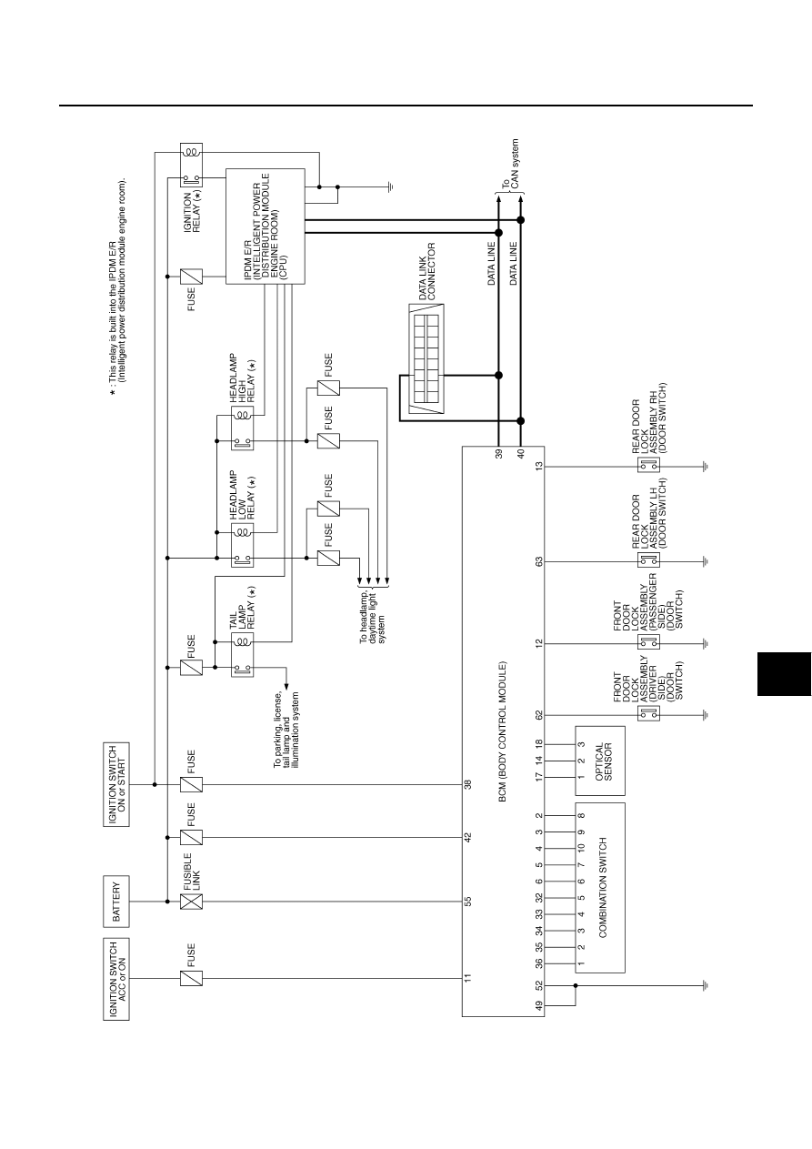
AUTO LIGHT SYSTEM
LT-89
C
D
E
F
G
H
I
J
L
M
A
B
LT
Revision: 2004 November
2004 Murano
Schematic
AKS004JM
TKWA1683E
|
|
|
AUTO LIGHT SYSTEM LT-89 C D E F G H I J L M A B LT Revision: 2004 November 2004 Murano Schematic AKS004JM TKWA1683E |